Part Strategy

Comments

Strategy name

Name of the strategy saved in the slm file

  • name: Strategy name

Strategy comment

Comments on the strategy saved in the slm file

  • comment: Strategy comment

Part comments

Place here you comments about anything related with part settings.

  • part_comments: Part comments

Scaling

X

Defines scaling factor in X direction (1.0 means unscaled)

ParameterScaleCenterPart.svg
  • scaling_x: X

Y

Defines scaling factor in Y direction (1.0 means unscaled)

ParameterScaleCenterPart.svg
  • scaling_y: Y

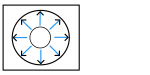
Z

Defines scaling factor in Z direction (1.0 means unscaled)

ParameterScaleCenterPart.svg
  • scaling_z: Z

Slicing

Slice thickness

Defines the distance between two layers. In other software it might be named as Layer thickness.

ParameterSliceThickness.svg
  • slice_thickness [mm]: Slice thickness

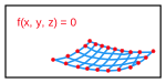
Implicit geometries

Minimum feature size

Defines the granularity of the implicit function evaluation. Set this to half the thickness of your thinnest detail. Example: For a lattice with 1 mm thick struts, set to 0.5 mm. To determine optimal value: identify the thinnest wall (e.g., 0.5 mm), set Min. Feature Size to half that value (0.25 mm or smaller), review the slices, and if geometry appears coarse or missing, continue halving the feature size until the result is smooth.

ParameterFeatureSize.svg
  • min_feature_size [mm]: Minimum feature size

Slice algorithm

nTop slicing algorithm to use. Dual Contouring (default): Best for CAD-like parts with sharp edges and flat planes. Maintains crisp corners using gradient information but may produce chevron artifacts in extremely thin-walled structures. Marching Squares: Ideal for complex/thin geometries like TPMS and dense lattices. More stable and robust in areas with geometric complexity, but will chamfer sharp corners. Use Marching Squares if Dual Contouring shows tool path errors or self-intersections.

  • slice_algorithm: Slice algorithm

    Options:

    • Dual Contouring (DualContouring)

    • Marching Squares (MarchingSquares)

Implicit debug mode

When enabled, CLI files will be created in the output folder immediately after slicing with the nTop core slicer. These files contain the raw slice data for debugging purposes.

  • implicit_debug_mode: Implicit debug mode

Gap fill

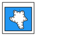
If enabled, fills in gaps in open contours.

ParameterGapFill.svg
  • fix_gapFill_enable: Gap fill

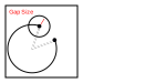
Max size

The threshold distance value for the gap fill.

ParameterGapSize.svg
  • fix_gapFill_maxSize [mm]: Max size

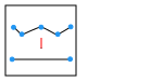
Point reduction

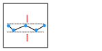
If enabled, the point reduction algorithm is used to reduce the amount of vectors. It works by merging successive vectors that lie on one line (within a given tolerance).

ParameterPointReduction.svg
  • optimize_pointReduction_enable: Point reduction

Point reduction tolerance

Points whose distance to a given vector is smaller than this value will be removed.

ParameterPointReductionTolerance.svg
  • optimize_pointReduction_tolerance: Point reduction tolerance

Contour filter

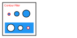
If enabled, automatically removes contours that are too small, e.g. Because they can not be represented accurately.

ParameterContourFilter.svg
  • optimize_contourFilter_enable: Contour filter

Min. length inner closed

Closed inner contours whose length is smaller than this value will be removed.

ParameterInnerContourLength.svg
  • optimize_contourFilter_minLengthInnerClosed [mm]: Min. length inner closed

Min. length outer closed

Closed outer contours whose length is smaller than this value will be removed.

ParameterOuterContourLength.svg
  • optimize_contourFilter_minLengthOuterClosed [mm]: Min. length outer closed

Overheat prevention

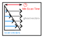
Enable or disable the overheat prevention mechanism during filling scans. When enabled, ghost vectors are added as needed to meet the minimum scan time.

ParameterOverHeatPreventionGeneral.svg
  • filling_overheat_prevention_enabled: Overheat prevention

    Overheat prevention min time

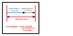
    Sets the minimum scan time (in seconds) required between two parallel filling vectors to prevent overheating. If the actual vector scan time is shorter, a ghost vector is added. Example: Minimum time = 0.5 s, actual vector time = 0.3 s → ghost vector must account for an extra 0.2 s.

    ParameterOverHeatPreventionParameters.svg
    • filling_overheat_prevention_min_time [s]: Overheat prevention min time

    Overheat prevention scan speed

    Defines the scan speed (in mm/s) for the ghost vector. Combined with the required delay, this determines the ghost vector’s length. Example: Extra time needed = 0.2 s, ghost speed = 500 mm/s → ghost vector length = 500 mm/s × 0.2 s = 100 mm.

    ParameterOverHeatPreventionParameters.svg
    • filling_overheat_prevention_scan_speed [mm/s]: Overheat prevention scan speed

Upskin

Max. surface angle

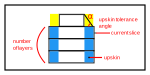
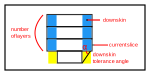
Indicates from which angle between 2 layers an area is seen as an upskin area.

It is used to limit and enhance the calculation of the upskin area. It filters out narrow sections regardless of the fact that single vectors may fit into the calculated area.

ParameterUpskin.svg
  • upskin_max_surf_angle [°]: Max. surface angle

    Upskin remelting

    If enabled, the top layers of a part would be treated as a

    separate zone. Upskin remelt is applied on top of a volume exposure.

    • upskin_remelting_enabled: Upskin remelting

      Skin generation

      Borders

      Enables borders for a complete part.

      • upskin_remelting_border_enabled: Borders

      Border offset

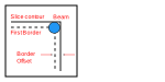
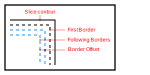
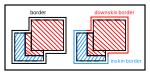
      Determines an offset between the original slice contour and the outermost border.

      ParameterBorderOffsetSingle.svg
      • upskin_remelting_border_offset [mm]: Border offset

      Filling

      Offset

      Defines by how much the fill area is reduced (positive values) or enlarged (negative values) compared to the initially calculated skin size. Positive values will result in a gap between the ends of the hatch vectors and the innermost border. Negative values will lead to an overlap of hatches and borders. Attention: high negative values can cause the hatch vectors to extend outside of the part boundary. This can lead to inferior surface quality and can even cause failure during job calculation.

      ParameterFillOffset.svg
      • upskin_remelting_fill_offset [mm]: Offset

      Pattern

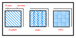
      Select a fill pattern (no pattern, stripe).

      ParameterFillPattern.svg
      • upskin_remelting_fill_pattern: Pattern

        Options:

        • No pattern (NoPattern)

        • Stripe (Stripe)

        • Chess (Chess)

      No pattern

      Hatch style

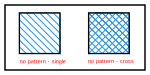
      Select a hatch style (single, cross, offset).

      ParameterFillNoPatternStyles.svg
      • upskin_remelting_fill_pattern_noPattern: Hatch style

        Options:

        • Single (Hatch)

        • Cross (Cross)

        • Offset (Offset)

      Hatch fill

      Distance

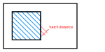
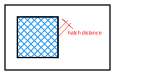
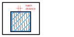
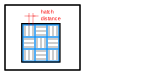
      Defines the distance between two neighbouring hatch vectors.

      ParameterFillNoPatternHatchDistance.svg
      • upskin_remelting_hatchFill_hatchDistance [mm]: Distance

      Filter length

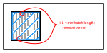
      Vectors shorter than this threshold will not be generated.

      ParameterFillNoPatternHatchFilterLength.svg
      • upskin_remelting_hatchFill_filter_length [mm]: Filter length

      Order

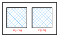
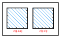
      Defines the sorting of the scanned vectors within the fill area.

      ParameterFillNoPatternHatchOrder.svg
      • upskin_remelting_hatchFill_sorting: Order

        Options:

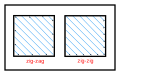
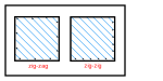
        • Bidirectional (ZigZag)

        • Unidirectional (ZigZig)

        • Bidirectional jump optimized (Optimized)

      Rotation angle

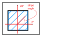
      Defines the angle of the fill pattern.

      ParameterFillNoPatternHatchAngles.svg
      • upskin_remelting_hatchFill_angle [°]: Rotation angle

      Limitation window enabled

      No vector with an angle inside of the prohibited range will be present in the output of this zone.

      ParameterFillAllPatternsLimitationWindowEnabled.svg
      • upskin_remelting_hatchFill_applySkipAngleRange: Limitation window enabled

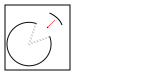
      Limitation window

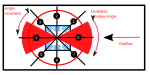
      Defines the circle sector facing the gas flow direction and containing range of vector angles which should not be present in the output if “Limitation window enabled” option is enabled in a part strategy.Every proposed pattern angle (starting with start angle and afterwards incrementing the previous one with angle increment) is first checked with respect to the limitation window. If the proposed pattern angle would result in a situation where one of the eventual hatch vectors lies within a limitation window, another pattern angle is proposed by incrementing the previous proposal with angle increment again. The process is repeated until a valid pattern angle is found (with a maximum of 100 attempts).the orientation and the sense of the angles can be controlled. For example, in the case of Single Fill, Unidirectional: by specifying 180 degrees as a limitation window, the orientation and the sense of the hatch vectors will be compatible with a gasflow of 0 degrees in a ‘strict interpretation’ (i.e., the gas flows right to left, the hatch vectors will be sorted left to right, and the sense of the hatch vectors is opposite to the gasflow).

      ParameterFillAllPatternsLimitationWindowEnabled.svg
      • upskin_remelting_hatchFill_skip_angle_window [°]: Limitation window

      Shift

      Shifts all hatch lines in Y direction by a half of hatch distance.

      ParameterFillNoPatternHatchShift.svg
      • upskin_remelting_hatchFill_shift_enabled: Shift

      Cross fill

      Distance

      Defines the distance between two neighbouring hatch vectors.

      ParameterFillNoPatternCrossHatchDistance.svg
      • upskin_remelting_crossFill_hatchDistance [mm]: Distance

      Filter length

      Vectors shorter than this threshold will not be generated.

      ParameterFillNoPatternStyles.svg
      • upskin_remelting_crossFill_filter_length [mm]: Filter length

      Order

      Defines the sorting of the scanned vectors within the fill area.

      ParameterFillNoPatternCrossHatchOrder.svg
      • upskin_remelting_crossFill_sorting: Order

        Options:

        • Bidirectional (ZigZag)

        • Unidirectional (ZigZig)

        • Bidirectional jump optimized (Optimized)

      Rotation angle

      Defines the angle of the fill pattern.

      ParameterFillNoPatternCrossHatchAngles.svg
      • upskin_remelting_crossFill_angle [°]: Rotation angle

      Limitation window enabled

      No vector with an angle inside of the prohibited range will be present in the output of this zone.

      ParameterFillAllPatternsLimitationWindowEnabled.svg
      • upskin_remelting_crossFill_applySkipAngleRange: Limitation window enabled

      Limitation window

      Defines the circle sector facing the gas flow direction and containing range of vector angles which should not be present in the output if “Limitation window enabled” option is enabled in a part strategy.Every proposed pattern angle (starting with start angle and afterwards incrementing the previous one with angle increment) is first checked with respect to the limitation window. If the proposed pattern angle would result in a situation where one of the eventual hatch vectors lies within a limitation window, another pattern angle is proposed by incrementing the previous proposal with angle increment again. The process is repeated until a valid pattern angle is found (with a maximum of 100 attempts).the orientation and the sense of the angles can be controlled. For example, in the case of Single Fill, Unidirectional: by specifying 180 degrees as a limitation window, the orientation and the sense of the hatch vectors will be compatible with a gasflow of 0 degrees in a ‘strict interpretation’ (i.e., the gas flows right to left, the hatch vectors will be sorted left to right, and the sense of the hatch vectors is opposite to the gasflow).

      ParameterFillAllPatternsLimitationWindowEnabled.svg
      • upskin_remelting_crossFill_skip_angle_window [°]: Limitation window

      Shift

      Shifts all hatch lines both in X and Y directions by a half of hatch distance.

      ParameterFillNoPatternCrossHatchShift.svg
      • upskin_remelting_crossFill_shift_enabled: Shift

      Offset fill

      Hatch distance

      Defines the distance between two neighbouring hatch vectors within each stripe.

      ParameterFillNoPatternOffsetHatchDistance.svg
      • upskin_remelting_offsetFill_hatchDistance [mm]: Hatch distance

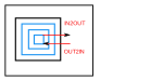
      Following borders ordering

      Select if the external following borders are scanned first and the internal ones later, or the opposite.

      ParameterFillNoPatternOrder.svg
      • upskin_remelting_offsetFill_sorting: Following borders ordering

        Options:

        • In to out (In2Out)

        • Out to in (Out2In)

      Blocked path

      When filling a contour with chess fields also very small pattern elements may be procuded. These areas would contain short hatch vectors that cannot be scanned optimally. To reduce the possibility of those short vectors occurance, small chess fields can be merged with neighbouring fields.

      ParameterBlockedPath.svg
      • upskin_remelting_offsetFill_blocked_path_enable: Blocked path

      Blocked path trim threshold

      ParameterBlockedPath.svg
      • upskin_remelting_offsetFill_blocked_path_trim_threshold [mm]: Blocked path trim threshold

      Stripe fill

      Hatch distance

      Defines the distance between two neighbouring hatch vectors within each stripe.

      ParameterFillStripesPatternHatchDistance.svg
      • upskin_remelting_stripeFill_hatchDistance [mm]: Hatch distance

      Stripe size

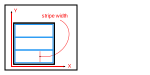
      Defines the width of the stripes.

      ParameterFillStripesPatternWidth.svg
      • upskin_remelting_stripeFill_patternSize [mm]: Stripe size

      Stripe offset

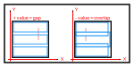
      Defines to which extent the stripes overlap or stand apart from each other. Positive values will result in a gap, negative values will lead to an overlap.

      ParameterFillStripesPatternOffset.svg
      • upskin_remelting_stripeFill_patternOffset [mm]: Stripe offset

      Shift factor

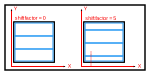
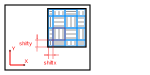
      Results in a “shift” of the entire “pattern” in y-direction. The original “Pattern” position will be reached after x iterations, with x being the entered value. The “Shift Factor” can be used in combination with rotation to perform a reference point relocation.

      ParameterFillStripesPatternShift.svg
      • upskin_remelting_stripeFill_shift: Shift factor

      Filter length

      Vectors shorter than this threshold will not be generated.

      ParameterFillStripesPatternMinimumHatchLength.svg
      • upskin_remelting_stripeFill_filter_length [mm]: Filter length

      Hatch sorting

      Defines the sorting of the scanned vectors within each stripe.

      ParameterFillStripesPatternHatchOrder.svg
      • upskin_remelting_stripeFill_sorting: Hatch sorting

        Options:

        • Bidirectional (ZigZag)

        • Unidirectional (ZigZig)

        • Bidirectional jump optimized (Optimized)

      Rotation angle

      Defines the angle of the fill pattern.

      ParameterFillStripesPatternAngle.svg
      • upskin_remelting_stripeFill_angle [°]: Rotation angle

      Limitation window enabled

      No vector with an angle inside of the prohibited range will be present in the output of this zone.

      ParameterFillAllPatternsLimitationWindowEnabled.svg
      • upskin_remelting_stripeFill_applySkipAngleRange: Limitation window enabled

      Limitation window

      Defines the circle sector facing the gas flow direction and containing range of vector angles which should not be present in the output if “Limitation window enabled” option is enabled in a part strategy.Every proposed pattern angle (starting with start angle and afterwards incrementing the previous one with angle increment) is first checked with respect to the limitation window. If the proposed pattern angle would result in a situation where one of the eventual hatch vectors lies within a limitation window, another pattern angle is proposed by incrementing the previous proposal with angle increment again. The process is repeated until a valid pattern angle is found (with a maximum of 100 attempts).the orientation and the sense of the angles can be controlled. For example, in the case of Single Fill, Unidirectional: by specifying 180 degrees as a limitation window, the orientation and the sense of the hatch vectors will be compatible with a gasflow of 0 degrees in a ‘strict interpretation’ (i.e., the gas flows right to left, the hatch vectors will be sorted left to right, and the sense of the hatch vectors is opposite to the gasflow).

      ParameterFillAllPatternsLimitationWindowEnabled.svg
      • upskin_remelting_stripeFill_skip_angle_window [°]: Limitation window

      Short vector optimization

      If enabled, vectors with a length equal or lower than the defined value will be merged with the colinear vector of a neighbouring stripe.

      ParameterFillStripesPatternHatchShortVectorOptimization.svg
      • upskin_remelting_stripeFill_shortVectorOptimization_enabled: Short vector optimization

      Merge length

      Vectors with a length equal or lower than the defined value will be merged with the colinear vector of a neighbouring stripe.

      ParameterFillStripesPatternHatchShortVectorOptimizationMergeLength.svg
      • upskin_remelting_stripeFill_shortVectorOptimization_thresholdLength [mm]: Merge length

      Chess fill

      Hatch distance

      Defines the distance between two neighbouring hatch vectors within each chess field.

      ParameterFillChessPatternHatchDistance.svg
      • upskin_remelting_chessFill_hatchDistance [mm]: Hatch distance

      Size X

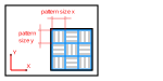
      Defines the desired size of the chess fields in X direction. The actual size will be the closest multiple of the value defined for the hatch distance.

      ParameterFillChessPatternPatternSize.svg
      • upskin_remelting_chessFill_patternSizeX [mm]: Size X

      Size Y

      Defines the desired size of the chess fields in Y direction. The actual size will be the closest multiple of the value defined for the hatch distance.

      ParameterFillChessPatternPatternSize.svg
      • upskin_remelting_chessFill_patternSizeY [mm]: Size Y

      Field offset

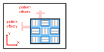
      Defines to which extent the chess fields overlap or stand apart from each other. Positive values will result in a gap, negative values will lead to an overlap.

      ParameterFillChessPatternPatternOffset.svg
      • upskin_remelting_chessFill_patternOffset [mm]: Field offset

      Filter length

      Vectors shorter than this threshold will not be generated.

      ParameterFillChessPatternHatchFilterLength.svg
      • upskin_remelting_chessFill_filter_length [mm]: Filter length

      Hatch sorting

      Defines the sorting of the scanned vectors within each chess field.

      ParameterFillChessPatternHatchOrder.svg
      • upskin_remelting_chessFill_sorting: Hatch sorting

        Options:

        • Bidirectional (ZigZag)

        • Unidirectional (ZigZig)

        • Bidirectional jump optimized (Optimized)

      Rotation angle

      Defines the angle of the fill pattern.

      ParameterFillChessPatternPatternAngles.svg
      • upskin_remelting_chessFill_startAngle [°]: Rotation angle

      Limitation window enabled

      No vector with an angle inside of the prohibited range will be present in the output of this zone.

      ParameterFillAllPatternsLimitationWindowEnabled.svg
      • upskin_remelting_chessFill_applySkipAngleRange: Limitation window enabled

      Limitation window

      Defines the circle sector facing the gas flow direction and containing range of vector angles which should not be present in the output if “Limitation window enabled” option is enabled in a part strategy.Every proposed pattern angle (starting with start angle and afterwards incrementing the previous one with angle increment) is first checked with respect to the limitation window. If the proposed pattern angle would result in a situation where one of the eventual hatch vectors lies within a limitation window, another pattern angle is proposed by incrementing the previous proposal with angle increment again. The process is repeated until a valid pattern angle is found (with a maximum of 100 attempts).the orientation and the sense of the angles can be controlled. For example, in the case of Single Fill, Unidirectional: by specifying 180 degrees as a limitation window, the orientation and the sense of the hatch vectors will be compatible with a gasflow of 0 degrees in a ‘strict interpretation’ (i.e., the gas flows right to left, the hatch vectors will be sorted left to right, and the sense of the hatch vectors is opposite to the gasflow).

      ParameterFillAllPatternsLimitationWindowEnabled.svg
      • upskin_remelting_chessFill_skip_angle_window [°]: Limitation window

      Shift factor

      Shifts the entire pattern in X and Y directions. The original pattern position will be reached after n iterations, with n being the value entered.

      ParameterFillChessPatternPatternShift.svg
      • upskin_remelting_chessFill_shift: Shift factor

      Filling orientation

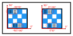
      Determines the orientation of the vectors of two adjacent chess fields.

      ParameterFillChessPatternFillOrientation.svg
      • upskin_remelting_chessFill_orientation: Filling orientation

        Options:

        • 90°/0° (NinetyZero)

        • 0°/90° (ZeroNinety)

        • 90°/90° (NinetyNinety)

        • 0°/0° (ZeroZero)

      Field output order

      ParameterFillChessPatternFillOrder.svg
      • upskin_remelting_chessFill_order: Field output order

        Options:

        • Field based (FieldBased)

        • Line based (LineBased)

        • In2Out (In2Out)

        • Out2In (Out2In)

      Small area optimization

      When filling a contour with chess fields also very small pattern elements may be procuded. These areas would contain short hatch vectors that cannot be scanned optimally. To reduce the possibility of those short vectors occurance, small chess fields can be merged with neighbouring fields.

      ParameterFillChessPatternPatternMerge.svg
      • upskin_remelting_chessFill_smallAreaOptimization_enabled: Small area optimization

      Minimal field size

      Defines the minimal length of chess field sides. Small chess fields will be merged with their neighbouring elements by extending the hatch vector length.

      ParameterFillChessPatternPatternMerge.svg
      • upskin_remelting_chessFill_minimalFieldSize [mm]: Minimal field size

    Upskin recoating

    If enabled, the top layers of a part would be treated as a

    separate zone. Upskin remelt is applied on top of a volume exposure.

    • upskin_recoating_enabled: Upskin recoating

      Skin generation

      Borders

      Enables borders for a complete part.

      • upskin_recoating_border_enabled: Borders

      Border offset

      Determines an offset between the original slice contour and the outermost border.

      ParameterBorderOffsetSingle.svg
      • upskin_recoating_border_offset [mm]: Border offset

      Filling

      Offset

      Defines by how much the fill area is reduced (positive values) or enlarged (negative values) compared to the initially calculated skin size. Positive values will result in a gap between the ends of the hatch vectors and the innermost border. Negative values will lead to an overlap of hatches and borders. Attention: high negative values can cause the hatch vectors to extend outside of the part boundary. This can lead to inferior surface quality and can even cause failure during job calculation.

      ParameterFillOffset.svg
      • upskin_recoating_fill_offset [mm]: Offset

      Pattern

      Select a fill pattern (no pattern, stripe).

      ParameterFillPattern.svg
      • upskin_recoating_fill_pattern: Pattern

        Options:

        • No pattern (NoPattern)

        • Stripe (Stripe)

        • Chess (Chess)

      No pattern

      Hatch style

      Select a hatch style (single, cross, offset).

      ParameterFillNoPatternStyles.svg
      • upskin_recoating_fill_pattern_noPattern: Hatch style

        Options:

        • Single (Hatch)

        • Cross (Cross)

        • Offset (Offset)

      Hatch fill

      Distance

      Defines the distance between two neighbouring hatch vectors.

      ParameterFillNoPatternHatchDistance.svg
      • upskin_recoating_hatchFill_hatchDistance [mm]: Distance

      Filter length

      Vectors shorter than this threshold will not be generated.

      ParameterFillNoPatternHatchFilterLength.svg
      • upskin_recoating_hatchFill_filter_length [mm]: Filter length

      Order

      Defines the sorting of the scanned vectors within the fill area.

      ParameterFillNoPatternHatchOrder.svg
      • upskin_recoating_hatchFill_sorting: Order

        Options:

        • Bidirectional (ZigZag)

        • Unidirectional (ZigZig)

        • Bidirectional jump optimized (Optimized)

      Rotation angle

      Defines the angle of the fill pattern.

      ParameterFillNoPatternHatchAngles.svg
      • upskin_recoating_hatchFill_angle [°]: Rotation angle

      Limitation window enabled

      No vector with an angle inside of the prohibited range will be present in the output of this zone.

      ParameterFillAllPatternsLimitationWindowEnabled.svg
      • upskin_recoating_hatchFill_applySkipAngleRange: Limitation window enabled

      Limitation window

      Defines the circle sector facing the gas flow direction and containing range of vector angles which should not be present in the output if “Limitation window enabled” option is enabled in a part strategy.Every proposed pattern angle (starting with start angle and afterwards incrementing the previous one with angle increment) is first checked with respect to the limitation window. If the proposed pattern angle would result in a situation where one of the eventual hatch vectors lies within a limitation window, another pattern angle is proposed by incrementing the previous proposal with angle increment again. The process is repeated until a valid pattern angle is found (with a maximum of 100 attempts).the orientation and the sense of the angles can be controlled. For example, in the case of Single Fill, Unidirectional: by specifying 180 degrees as a limitation window, the orientation and the sense of the hatch vectors will be compatible with a gasflow of 0 degrees in a ‘strict interpretation’ (i.e., the gas flows right to left, the hatch vectors will be sorted left to right, and the sense of the hatch vectors is opposite to the gasflow).

      ParameterFillAllPatternsLimitationWindowEnabled.svg
      • upskin_recoating_hatchFill_skip_angle_window [°]: Limitation window

      Shift

      Shifts all hatch lines in Y direction by a half of hatch distance.

      ParameterFillNoPatternHatchShift.svg
      • upskin_recoating_hatchFill_shift_enabled: Shift

      Cross fill

      Distance

      Defines the distance between two neighbouring hatch vectors.

      ParameterFillNoPatternCrossHatchDistance.svg
      • upskin_recoating_crossFill_hatchDistance [mm]: Distance

      Filter length

      Vectors shorter than this threshold will not be generated.

      ParameterFillNoPatternCrossHatchFilterLength.svg
      • upskin_recoating_crossFill_filter_length [mm]: Filter length

      Order

      Defines the sorting of the scanned vectors within the fill area.

      ParameterFillNoPatternCrossHatchOrder.svg
      • upskin_recoating_crossFill_sorting: Order

        Options:

        • Bidirectional (ZigZag)

        • Unidirectional (ZigZig)

        • Bidirectional jump optimized (Optimized)

      Rotation angle

      Defines the angle of the fill pattern.

      ParameterFillNoPatternCrossHatchAngles.svg
      • upskin_recoating_crossFill_angle [°]: Rotation angle

      Limitation window enabled

      No vector with an angle inside of the prohibited range will be present in the output of this zone.

      ParameterFillAllPatternsLimitationWindowEnabled.svg
      • upskin_recoating_crossFill_applySkipAngleRange: Limitation window enabled

      Limitation window

      Defines the circle sector facing the gas flow direction and containing range of vector angles which should not be present in the output if “Limitation window enabled” option is enabled in a part strategy.Every proposed pattern angle (starting with start angle and afterwards incrementing the previous one with angle increment) is first checked with respect to the limitation window. If the proposed pattern angle would result in a situation where one of the eventual hatch vectors lies within a limitation window, another pattern angle is proposed by incrementing the previous proposal with angle increment again. The process is repeated until a valid pattern angle is found (with a maximum of 100 attempts).the orientation and the sense of the angles can be controlled. For example, in the case of Single Fill, Unidirectional: by specifying 180 degrees as a limitation window, the orientation and the sense of the hatch vectors will be compatible with a gasflow of 0 degrees in a ‘strict interpretation’ (i.e., the gas flows right to left, the hatch vectors will be sorted left to right, and the sense of the hatch vectors is opposite to the gasflow).

      ParameterFillAllPatternsLimitationWindowEnabled.svg
      • upskin_recoating_crossFill_skip_angle_window [°]: Limitation window

      Shift

      Shifts all hatch lines both in X and Y directions by a half of hatch distance.

      ParameterFillNoPatternCrossHatchShift.svg
      • upskin_recoating_crossFill_shift_enabled: Shift

      Offset fill

      Hatch distance

      Defines the distance between two neighbouring hatch vectors within each stripe.

      ParameterFillNoPatternOffsetHatchDistance.svg
      • upskin_recoating_offsetFill_hatchDistance [mm]: Hatch distance

      Following borders ordering

      Select if the external following borders are scanned first and the internal ones later, or the opposite.

      ParameterFillNoPatternOrder.svg
      • upskin_recoating_offsetFill_sorting: Following borders ordering

        Options:

        • In to out (In2Out)

        • Out to in (Out2In)

      Blocked path

      When filling a contour with chess fields also very small pattern elements may be procuded. These areas would contain short hatch vectors that cannot be scanned optimally. To reduce the possibility of those short vectors occurance, small chess fields can be merged with neighbouring fields.

      ParameterBlockedPath.svg
      • upskin_recoating_offsetFill_blocked_path_enable: Blocked path

      Blocked path trim threshold

      ParameterTrimmedBlockedPath.svg
      • upskin_recoating_offsetFill_blocked_path_trim_threshold [mm]: Blocked path trim threshold

      Stripe fill

      Hatch distance

      Defines the distance between two neighbouring hatch vectors within each stripe.

      ParameterFillStripesPatternHatchDistance.svg
      • upskin_recoating_stripeFill_hatchDistance [mm]: Hatch distance

      Stripe size

      Defines the width of the stripes.

      ParameterFillStripesPatternWidth.svg
      • upskin_recoating_stripeFill_patternSize [mm]: Stripe size

      Stripe offset

      Defines to which extent the stripes overlap or stand apart from each other. Positive values will result in a gap, negative values will lead to an overlap.

      ParameterFillStripesPatternOffset.svg
      • upskin_recoating_stripeFill_patternOffset [mm]: Stripe offset

      Shift factor

      Results in a “shift” of the entire “pattern” in y-direction. The original “Pattern” position will be reached after x iterations, with x being the entered value. The “Shift Factor” can be used in combination with rotation to perform a reference point relocation.

      ParameterFillStripesPatternShift.svg
      • upskin_recoating_stripeFill_shift: Shift factor

      Filter length

      Vectors shorter than this threshold will not be generated.

      ParameterFillStripesPatternMinimumHatchLength.svg
      • upskin_recoating_stripeFill_filter_length [mm]: Filter length

      Hatch sorting

      Defines the sorting of the scanned vectors within each stripe.

      ParameterFillStripesPatternHatchOrder.svg
      • upskin_recoating_stripeFill_sorting: Hatch sorting

        Options:

        • Bidirectional (ZigZag)

        • Unidirectional (ZigZig)

        • Bidirectional jump optimized (Optimized)

      Rotation angle

      Defines the angle of the fill pattern.

      ParameterFillStripesPatternAngle.svg
      • upskin_recoating_stripeFill_angle [°]: Rotation angle

      Limitation window enabled

      No vector with an angle inside of the prohibited range will be present in the output of this zone.

      ParameterFillAllPatternsLimitationWindowEnabled.svg
      • upskin_recoating_stripeFill_applySkipAngleRange: Limitation window enabled

      Limitation window

      Defines the circle sector facing the gas flow direction and containing range of vector angles which should not be present in the output if “Limitation window enabled” option is enabled in a part strategy.Every proposed pattern angle (starting with start angle and afterwards incrementing the previous one with angle increment) is first checked with respect to the limitation window. If the proposed pattern angle would result in a situation where one of the eventual hatch vectors lies within a limitation window, another pattern angle is proposed by incrementing the previous proposal with angle increment again. The process is repeated until a valid pattern angle is found (with a maximum of 100 attempts).the orientation and the sense of the angles can be controlled. For example, in the case of Single Fill, Unidirectional: by specifying 180 degrees as a limitation window, the orientation and the sense of the hatch vectors will be compatible with a gasflow of 0 degrees in a ‘strict interpretation’ (i.e., the gas flows right to left, the hatch vectors will be sorted left to right, and the sense of the hatch vectors is opposite to the gasflow).

      ParameterFillAllPatternsLimitationWindowEnabled.svg
      • upskin_recoating_stripeFill_skip_angle_window [°]: Limitation window

      Short vector optimization

      If enabled, vectors with a length equal or lower than the defined value will be merged with the colinear vector of a neighbouring stripe.

      ParameterFillStripesPatternHatchShortVectorOptimization.svg
      • upskin_recoating_stripeFill_shortVectorOptimization_enabled: Short vector optimization

      Merge length

      Vectors with a length equal or lower than the defined value will be merged with the colinear vector of a neighbouring stripe.

      ParameterFillStripesPatternHatchShortVectorOptimizationMergeLength.svg
      • upskin_recoating_stripeFill_shortVectorOptimization_thresholdLength [mm]: Merge length

      Chess fill

      Hatch distance

      Defines the distance between two neighbouring hatch vectors within each chess field.

      ParameterFillChessPatternHatchDistance.svg
      • upskin_recoating_chessFill_hatchDistance [mm]: Hatch distance

      Size X

      Defines the desired size of the chess fields in X direction. The actual size will be the closest multiple of the value defined for the hatch distance.

      ParameterFillChessPatternPatternSize.svg
      • upskin_recoating_chessFill_patternSizeX [mm]: Size X

      Size Y

      Defines the desired size of the chess fields in Y direction. The actual size will be the closest multiple of the value defined for the hatch distance.

      ParameterFillChessPatternPatternSize.svg
      • upskin_recoating_chessFill_patternSizeY [mm]: Size Y

      Field offset

      Defines to which extent the chess fields overlap or stand apart from each other. Positive values will result in a gap, negative values will lead to an overlap.

      ParameterFillChessPatternPatternOffset.svg
      • upskin_recoating_chessFill_patternOffset [mm]: Field offset

      Filter length

      Vectors shorter than this threshold will not be generated.

      ParameterFillChessPatternHatchFilterLength.svg
      • upskin_recoating_chessFill_filter_length [mm]: Filter length

      Hatch sorting

      Defines the sorting of the scanned vectors within each chess field.

      ParameterFillChessPatternHatchOrder.svg
      • upskin_recoating_chessFill_sorting: Hatch sorting

        Options:

        • Bidirectional (ZigZag)

        • Unidirectional (ZigZig)

        • Bidirectional jump optimized (Optimized)

      Rotation angle

      Defines the angle of the fill pattern.

      ParameterFillChessPatternPatternAngles.svg
      • upskin_recoating_chessFill_startAngle [°]: Rotation angle

      Limitation window enabled

      No vector with an angle inside of the prohibited range will be present in the output of this zone.

      ParameterFillAllPatternsLimitationWindowEnabled.svg
      • upskin_recoating_chessFill_applySkipAngleRange: Limitation window enabled

      Limitation window

      Defines the circle sector facing the gas flow direction and containing range of vector angles which should not be present in the output if “Limitation window enabled” option is enabled in a part strategy.Every proposed pattern angle (starting with start angle and afterwards incrementing the previous one with angle increment) is first checked with respect to the limitation window. If the proposed pattern angle would result in a situation where one of the eventual hatch vectors lies within a limitation window, another pattern angle is proposed by incrementing the previous proposal with angle increment again. The process is repeated until a valid pattern angle is found (with a maximum of 100 attempts).the orientation and the sense of the angles can be controlled. For example, in the case of Single Fill, Unidirectional: by specifying 180 degrees as a limitation window, the orientation and the sense of the hatch vectors will be compatible with a gasflow of 0 degrees in a ‘strict interpretation’ (i.e., the gas flows right to left, the hatch vectors will be sorted left to right, and the sense of the hatch vectors is opposite to the gasflow).

      ParameterFillAllPatternsLimitationWindowEnabled.svg
      • upskin_recoating_chessFill_skip_angle_window [°]: Limitation window

      Shift factor

      Shifts the entire pattern in X and Y directions. The original pattern position will be reached after n iterations, with n being the value entered.

      ParameterFillChessPatternPatternShift.svg
      • upskin_recoating_chessFill_shift: Shift factor

      Filling orientation

      Determines the orientation of the vectors of two adjacent chess fields.

      ParameterFillChessPatternFillOrientation.svg
      • upskin_recoating_chessFill_orientation: Filling orientation

        Options:

        • 90°/0° (NinetyZero)

        • 0°/90° (ZeroNinety)

        • 90°/90° (NinetyNinety)

        • 0°/0° (ZeroZero)

      Field output order

      ParameterFillChessPatternFillOrder.svg
      • upskin_recoating_chessFill_order: Field output order

        Options:

        • Field based (FieldBased)

        • Line based (LineBased)

        • In2Out (In2Out)

        • Out2In (Out2In)

      Small area optimization

      When filling a contour with chess fields also very small pattern elements may be procuded. These areas would contain short hatch vectors that cannot be scanned optimally. To reduce the possibility of those short vectors occurance, small chess fields can be merged with neighbouring fields.

      ParameterFillChessPatternPatternMerge.svg
      • upskin_recoating_chessFill_smallAreaOptimization_enabled: Small area optimization

      Minimal field size

      Defines the minimal length of chess field sides. Small chess fields will be merged with their neighbouring elements by extending the hatch vector length.

      ParameterFillChessPatternPatternMerge.svg
      • upskin_recoating_chessFill_minimalFieldSize [mm]: Minimal field size

Volume

Borders

Enables borders for a complete part.

  • border_enabled: Borders

    Start Point Relocation Mode

    Select an algorithm which is used to define the first point of each layer.

    ParameterBorderStartPointRelocation.svg
    • border_startPointRelocation_type: Start Point Relocation Mode

      Options:

      • None (None)

      • Random (Random)

    Beam compensation

    Determines an offset between the original slice contour and the outermost border.

    ParameterBorderOffsetSingle.svg
    • border_offset [mm]: Beam compensation

    Additional borders

    ParameterBorderOffset.svg
    • border_following: Additional borders

      Columns:

      Border offset

      ParameterBorderOffsetSingle.svg
      • border_offset [mm]: Border offset

    Fill contour

    Enable an additional innermost border before hatching starts. This provides a smoother transition between borders and hatching.

    • fill_contour_enabled: Fill contour

    Fill contour offset

    Offset for the fill contour from the innermost following border.

    • fill_contour_offset [mm]: Fill contour offset

    Additional fill contours

    • fill_contour_following: Additional fill contours

      Columns:

      Border offset

      ParameterBorderOffsetSingle.svg
      • border_offset [mm]: Border offset

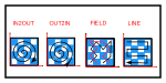
    Borders ordering

    Select if the external borders are scanned first and the internal ones later, or viceversa.

    ParameterBorderOrder.svg
    • border_order: Borders ordering

      Options:

      • In to out (In2Out)

      • Out to in (Out2In)

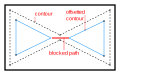
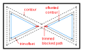
    Border optimization

    Optimizes the quality of small areas like thin walls and sharp edges. In areas thinner than twice the beam compensation (outermost border) or border offset (following borders), blocked paths segments are created . When disabled those thin areas will not be scanned at all.

    ParameterBlockedPath.svg
    • borderOptimization_enabled: Border optimization

      Blocked path

      Scan twice

      If checkbox is disabled blocked paths will be scanned once.

      ParameterBlockedPathTwice.svg
      • borderOptimization_scan_twice: Scan twice

      Trim threshold

      Determines the offset contour for trimming the blocked path. Outermost borders are never trimmed.

      ParameterTrimmedBlockedPath.svg
      • borderOptimization_trimThreshold: Trim threshold

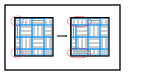
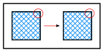
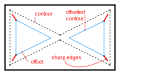
      Sharp edges

      Helps to avoid uncovered areas in sharp edges during building caused by the beam compensation in combination with the shape of the laser beam.

      ParameterSharpEdges.svg
      • borderOptimization_sharpEdges: Sharp edges

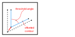
      Max angle

      Two vectors form a corner of a given angle. When this angle is below the ‘Max. angle’ the corner is considered a sharp edge and subject to optimization.

      ParameterSharpEdgesThresholdAngle.svg
      • borderOptimization_maxAngle [°]: Max angle

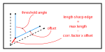
      Correction factor

      Is multiplied by ‘Beam compensation’ (for the first border) or by ‘Border distance’ (for following borders). The resulting value is subtracted from the length of the blocked path for the sharp edge. This defines the length of the segment that is scanned additionally in a corner between the original slice contour and the beam-compensated border. The larger the value for ‘Correction factor’ the shorter the segment that is scanned additionally.

      ParameterSharpEdgesCorrectionFactor.svg
      • borderOptimization_correctionFactor: Correction factor

Hatching

  • volume_hatching_enabled: Hatching

Hatch every … layers

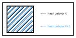
Controls the number of volume layers to be scanned. For example, the value 1 will make sure all volume layers are scanned, while the value 3 will cause all second and third layer to be skipped.

  • volume_hatching_every_xlayers: Hatch every … layers

Offset

Defines by how much the fill area is reduced (positive values) or enlarged (negative values) compared to the initially calculated skin size. Positive values will result in a gap between the ends of the hatch vectors and the innermost border. Negative values will lead to an overlap of hatches and borders. Attention: high negative values can cause the hatch vectors to extend outside of the part boundary. This can lead to inferior surface quality and can even cause failure during job calculation.

ParameterFillOffset.svg
  • volume_fill_offset [mm]: Offset

Pattern

Select a fill pattern (no pattern, stripe).

ParameterFillPattern.svg
  • volume_fill_pattern: Pattern

    Options:

    • No pattern (NoPattern)

    • Stripe (Stripe)

    • Chess (Chess)

No pattern

Hatch style

Select a hatch style (single, cross, offset).

ParameterFillNoPatternStyles.svg
  • volume_fill_pattern_noPattern: Hatch style

    Options:

    • Single (Hatch)

    • Cross (Cross)

    • Offset (Offset)

Hatch fill

Distance

Defines the distance between two neighbouring hatch vectors.

ParameterFillNoPatternHatchDistance.svg
  • volume_hatchFill_hatchDistance [mm]: Distance

Filter length

Vectors shorter than this threshold will not be generated.

ParameterFillNoPatternHatchFilterLength.svg
  • volume_hatchFill_filter_length [mm]: Filter length

Order

Defines the sorting of the scanned vectors within the fill area.

ParameterFillNoPatternHatchOrder.svg
  • volume_hatchFill_sorting: Order

    Options:

    • Bidirectional (ZigZag)

    • Unidirectional (ZigZig)

    • Bidirectional jump optimized (Optimized)

Rotation start angle

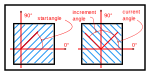
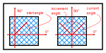
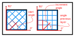
Defines the initial start angle from which rotation of the fill vectors starts.

ParameterFillNoPatternHatchAngles.svg
  • volume_hatchFill_angle [°]: Rotation start angle

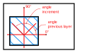
Rotation increment angle

Defines the increment value of the rotation angle between consecutive layers.

ParameterFillNoPatternHatchAngles.svg
  • volume_hatchFill_incrementAngle [°]: Rotation increment angle

Limitation window enabled

No vector with an angle inside of the prohibited range will be present in the output of this zone.

ParameterFillAllPatternsLimitationWindowEnabled.svg
  • volume_hatchFill_applySkipAngleRange: Limitation window enabled

Limitation window

Defines the circle sector facing the gas flow direction and containing range of vector angles which should not be present in the output if “Limitation window enabled” option is enabled in a part strategy.Every proposed pattern angle (starting with start angle and afterwards incrementing the previous one with angle increment) is first checked with respect to the limitation window. If the proposed pattern angle would result in a situation where one of the eventual hatch vectors lies within a limitation window, another pattern angle is proposed by incrementing the previous proposal with angle increment again. The process is repeated until a valid pattern angle is found (with a maximum of 100 attempts).the orientation and the sense of the angles can be controlled. For example, in the case of Single Fill, Unidirectional: by specifying 180 degrees as a limitation window, the orientation and the sense of the hatch vectors will be compatible with a gasflow of 0 degrees in a ‘strict interpretation’ (i.e., the gas flows right to left, the hatch vectors will be sorted left to right, and the sense of the hatch vectors is opposite to the gasflow).

ParameterFillAllPatternsLimitationWindowEnabled.svg
  • volume_hatchFill_skip_angle_window [°]: Limitation window

Shift

Shifts all hatch lines in Y direction by a half of hatch distance.

ParameterFillNoPatternHatchShift.svg
  • volume_hatchFill_shift_enabled: Shift

Cross fill

Distance

Defines the distance between two neighbouring hatch vectors.

ParameterFillNoPatternCrossHatchDistance.svg
  • volume_crossFill_hatchDistance [mm]: Distance

Filter length

Vectors shorter than this threshold will not be generated.

ParameterFillNoPatternCrossHatchFilterLength.svg
  • volume_crossFill_filter_length [mm]: Filter length

Order

Defines the sorting of the scanned vectors within the fill area.

ParameterFillNoPatternCrossHatchOrder.svg
  • volume_crossFill_sorting: Order

    Options:

    • Bidirectional (ZigZag)

    • Unidirectional (ZigZig)

    • Bidirectional jump optimized (Optimized)

Rotation start angle

Defines the initial start angle from which rotation of the fill vectors starts.

ParameterFillNoPatternCrossHatchAngles.svg
  • volume_crossFill_angle [°]: Rotation start angle

Rotation increment angle

Defines the increment value of the rotation angle between consecutive layers.

ParameterFillNoPatternCrossHatchAngles.svg
  • volume_crossFill_incrementAngle [°]: Rotation increment angle

Limitation window enabled

No vector with an angle inside of the prohibited range will be present in the output of this zone.

ParameterFillAllPatternsLimitationWindowEnabled.svg
  • volume_crossFill_applySkipAngleRange: Limitation window enabled

Limitation window

Defines the circle sector facing the gas flow direction and containing range of vector angles which should not be present in the output if “Limitation window enabled” option is enabled in a part strategy.Every proposed pattern angle (starting with start angle and afterwards incrementing the previous one with angle increment) is first checked with respect to the limitation window. If the proposed pattern angle would result in a situation where one of the eventual hatch vectors lies within a limitation window, another pattern angle is proposed by incrementing the previous proposal with angle increment again. The process is repeated until a valid pattern angle is found (with a maximum of 100 attempts).the orientation and the sense of the angles can be controlled. For example, in the case of Single Fill, Unidirectional: by specifying 180 degrees as a limitation window, the orientation and the sense of the hatch vectors will be compatible with a gasflow of 0 degrees in a ‘strict interpretation’ (i.e., the gas flows right to left, the hatch vectors will be sorted left to right, and the sense of the hatch vectors is opposite to the gasflow).

ParameterFillAllPatternsLimitationWindowEnabled.svg
  • volume_crossFill_skip_angle_window [°]: Limitation window

Shift

Shifts all hatch lines both in X and Y directions by a half of hatch distance.

ParameterFillNoPatternCrossHatchShift.svg
  • volume_crossFill_shift_enabled: Shift

Offset fill

Hatch distance

Defines the distance between two neighbouring hatch vectors within each stripe.

ParameterFillNoPatternOffsetHatchDistance.svg
  • volume_offsetFill_hatchDistance [mm]: Hatch distance

Following borders ordering

Select if the external following borders are scanned first and the internal ones later, or the opposite.

ParameterFillNoPatternOrder.svg
  • volume_offsetFill_sorting: Following borders ordering

    Options:

    • In to out (In2Out)

    • Out to in (Out2In)

Blocked path

When filling a contour with chess fields also very small pattern elements may be procuded. These areas would contain short hatch vectors that cannot be scanned optimally. To reduce the possibility of those short vectors occurance, small chess fields can be merged with neighbouring fields.

ParameterBlockedPath.svg
  • volume_offsetFill_blocked_path_enable: Blocked path

Blocked path trim threshold

ParameterTrimmedBlockedPath.svg
  • volume_offsetFill_blocked_path_trim_threshold [mm]: Blocked path trim threshold

Stripe fill

Hatch distance

Defines the distance between two neighbouring hatch vectors within each stripe.

ParameterFillStripesPatternHatchDistance.svg
  • volume_stripeFill_hatchDistance [mm]: Hatch distance

Stripe size

Defines the width of the stripes.

ParameterFillStripesPatternWidth.svg
  • volume_stripeFill_patternSize [mm]: Stripe size

Stripe offset

Defines to which extent the stripes overlap or stand apart from each other. Positive values will result in a gap, negative values will lead to an overlap.

ParameterFillStripesPatternOffset.svg
  • volume_stripeFill_patternOffset [mm]: Stripe offset

Shift factor

Results in a “shift” of the entire “pattern” in y-direction. The original “Pattern” position will be reached after x iterations, with x being the entered value. The “Shift Factor” can be used in combination with rotation to perform a reference point relocation.

ParameterFillStripesPatternShift.svg
  • volume_stripeFill_shift: Shift factor

Filter length

Vectors shorter than this threshold will not be generated.

ParameterFillStripesPatternMinimumHatchLength.svg
  • volume_stripeFill_filter_length [mm]: Filter length

Hatch sorting

Defines the sorting of the scanned vectors within each stripe.

ParameterFillStripesPatternHatchOrder.svg
  • volume_stripeFill_sorting: Hatch sorting

    Options:

    • Bidirectional (ZigZag)

    • Unidirectional (ZigZig)

    • Bidirectional jump optimized (Optimized)

Rotation start angle

Defines the initial start angle from which rotation of the fill vectors starts.

ParameterFillStripesPatternAngle.svg
  • volume_stripeFill_angle [°]: Rotation start angle

Rotation increment

Defines the increment value of the rotation angle between consecutive layers.

ParameterFillStripesPatternAngleIncrement.svg
  • volume_stripeFill_incrementAngle [°]: Rotation increment

Limitation window enabled

No vector with an angle inside of the prohibited range will be present in the output of this zone.

ParameterFillAllPatternsLimitationWindowEnabled.svg
  • volume_stripeFill_applySkipAngleRange: Limitation window enabled

Limitation window

Defines the circle sector facing the gas flow direction and containing range of vector angles which should not be present in the output if “Limitation window enabled” option is enabled in a part strategy.Every proposed pattern angle (starting with start angle and afterwards incrementing the previous one with angle increment) is first checked with respect to the limitation window. If the proposed pattern angle would result in a situation where one of the eventual hatch vectors lies within a limitation window, another pattern angle is proposed by incrementing the previous proposal with angle increment again. The process is repeated until a valid pattern angle is found (with a maximum of 100 attempts).the orientation and the sense of the angles can be controlled. For example, in the case of Single Fill, Unidirectional: by specifying 180 degrees as a limitation window, the orientation and the sense of the hatch vectors will be compatible with a gasflow of 0 degrees in a ‘strict interpretation’ (i.e., the gas flows right to left, the hatch vectors will be sorted left to right, and the sense of the hatch vectors is opposite to the gasflow).

ParameterFillAllPatternsLimitationWindowEnabled.svg
  • volume_stripeFill_skip_angle_window [°]: Limitation window

Short vector optimization

If enabled, vectors with a length equal or lower than the defined value will be merged with the colinear vector of a neighbouring stripe.

ParameterFillStripesPatternHatchShortVectorOptimization.svg
  • volume_stripeFill_shortVectorOptimization_enabled: Short vector optimization

Merge length

Vectors with a length equal or lower than the defined value will be merged with the colinear vector of a neighbouring stripe.

ParameterFillStripesPatternHatchShortVectorOptimizationMergeLength.svg
  • volume_stripeFill_shortVectorOptimization_thresholdLength [mm]: Merge length

Chess fill

Hatch distance

Defines the distance between two neighbouring hatch vectors within each chess field.

ParameterFillChessPatternHatchDistance.svg
  • volume_chessFill_hatchDistance [mm]: Hatch distance

Size X

Defines the desired size of the chess fields in X direction. The actual size will be the closest multiple of the value defined for the hatch distance.

ParameterFillChessPatternPatternSize.svg
  • volume_chessFill_patternSizeX [mm]: Size X

Size Y

Defines the desired size of the chess fields in Y direction. The actual size will be the closest multiple of the value defined for the hatch distance.

ParameterFillChessPatternPatternSize.svg
  • volume_chessFill_patternSizeY [mm]: Size Y

Field offset

Defines to which extent the chess fields overlap or stand apart from each other. Positive values will result in a gap, negative values will lead to an overlap.

ParameterFillChessPatternPatternOffset.svg
  • volume_chessFill_patternOffset [mm]: Field offset

Filter length

Vectors shorter than this threshold will not be generated.

ParameterFillChessPatternHatchFilterLength.svg
  • volume_chessFill_filter_length [mm]: Filter length

Hatch sorting

Defines the sorting of the scanned vectors within each chess field.

ParameterFillChessPatternHatchOrder.svg
  • volume_chessFill_sorting: Hatch sorting

    Options:

    • Bidirectional (ZigZag)

    • Unidirectional (ZigZig)

    • Bidirectional jump optimized (Optimized)

Rotation start angle

Defines the initial start angle from which rotation of the fill vectors starts.

ParameterFillChessPatternPatternAngles.svg
  • volume_chessFill_startAngle [°]: Rotation start angle

Rotation increment

Defines the increment value of the rotation angle between consecutive layers.

ParameterFillChessPatternPatternAngles.svg
  • volume_chessFill_incrementAngle [°]: Rotation increment

Limitation window enabled

No vector with an angle inside of the prohibited range will be present in the output of this zone.

ParameterFillAllPatternsLimitationWindowEnabled.svg
  • volume_chessFill_applySkipAngleRange: Limitation window enabled

Limitation window

Defines the circle sector facing the gas flow direction and containing range of vector angles which should not be present in the output if “Limitation window enabled” option is enabled in a part strategy.Every proposed pattern angle (starting with start angle and afterwards incrementing the previous one with angle increment) is first checked with respect to the limitation window. If the proposed pattern angle would result in a situation where one of the eventual hatch vectors lies within a limitation window, another pattern angle is proposed by incrementing the previous proposal with angle increment again. The process is repeated until a valid pattern angle is found (with a maximum of 100 attempts).the orientation and the sense of the angles can be controlled. For example, in the case of Single Fill, Unidirectional: by specifying 180 degrees as a limitation window, the orientation and the sense of the hatch vectors will be compatible with a gasflow of 0 degrees in a ‘strict interpretation’ (i.e., the gas flows right to left, the hatch vectors will be sorted left to right, and the sense of the hatch vectors is opposite to the gasflow).

ParameterFillAllPatternsLimitationWindowEnabled.svg
  • volume_chessFill_skip_angle_window [°]: Limitation window

Shift factor

Shifts the entire pattern in X and Y directions. The original pattern position will be reached after n iterations, with n being the value entered.

ParameterFillChessPatternPatternShift.svg
  • volume_chessFill_shift: Shift factor

Filling orientation

Determines the orientation of the vectors of two adjacent chess fields.

ParameterFillChessPatternFillOrientation.svg
  • volume_chessFill_orientation: Filling orientation

    Options:

    • 90°/0° (NinetyZero)

    • 0°/90° (ZeroNinety)

    • 90°/90° (NinetyNinety)

    • 0°/0° (ZeroZero)

Field output order

ParameterFillChessPatternFillOrder.svg
  • volume_chessFill_order: Field output order

    Options:

    • Field based (FieldBased)

    • Line based (LineBased)

    • In2Out (In2Out)

    • Out2In (Out2In)

Small area optimization

When filling a contour with chess fields also very small pattern elements may be procuded. These areas would contain short hatch vectors that cannot be scanned optimally. To reduce the possibility of those short vectors occurance, small chess fields can be merged with neighbouring fields.

ParameterFillChessPatternPatternMerge.svg
  • volume_chessFill_smallAreaOptimization_enabled: Small area optimization

Minimal field size

Defines the minimal length of chess field sides. Small chess fields will be merged with their neighbouring elements by extending the hatch vector length.

ParameterFillChessPatternPatternMerge.svg
  • volume_chessFill_minimalFieldSize [mm]: Minimal field size

Volume Core

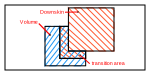
If enabled, Core will be treated as a separate zone. In the terminology of hull & core the volume section indicates the settings for the hull and the volume core section indicates the settings for the core. If no core is present the volume core settings are skipped.

  • core_enabled: Volume Core

Hatch every … layers

Controls the number of core layers to be scanned. For example, the value 1 will make sure all core layers are scanned, while the value 3 will cause all second and third layer to be skipped. It is worth noting that core cannot be hatched without a hull (volume).

  • core_every_xlayers: Hatch every … layers

    Transition Contours

    • core_fill_contour_enabled: Transition Contours

    Transition Contours Offset

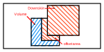
    Defines by how much the hull zone is reduced (positive values) compared to the initially calculated skin size.

    • core_fill_contour_offset [mm]: Transition Contours Offset

    Number of Transition Contours

    • core_fill_contour_number_of_border [ ]: Number of Transition Contours

    Transition Contours Distance

    Distance between transition contours.

    • core_fill_contour_distance [mm]: Transition Contours Distance

    Transition Contours order

    Select if the external transition contours are scanned first and the internal ones later, or viceversa.

    • core_fill_contour_order: Transition Contours order

      Options:

      • In to out (In2Out)

      • Out to in (Out2In)

    Hatching

    • core_hatching_enabled: Hatching

    Offset

    Defines the offset given to the fill area in relation with the hull and core boundary. Positive values will make the fill area smaller negative values make the fill area overlap the border.

    ParameterFillOffset.svg
    • core_fill_offset [mm]: Offset

    Pattern

    Select a fill pattern (no pattern, stripe).

    ParameterFillPattern.svg
    • core_fill_pattern: Pattern

      Options:

      • No pattern (NoPattern)

      • Stripe (Stripe)

      • Chess (Chess)

    No pattern

    Hatch style

    Select a hatch style (single, cross).

    ParameterFillNoPatternStyles.svg
    • core_fill_pattern_noPattern: Hatch style

      Options:

      • Single (Hatch)

      • Cross (Cross)

    Hatch fill

    Distance

    Defines the distance between two neighbouring hatch vectors.

    ParameterFillNoPatternHatchDistance.svg
    • core_hatchFill_hatchDistance [mm]: Distance

    Filter length

    Vectors shorter than this threshold will not be generated.

    ParameterFillNoPatternHatchFilterLength.svg
    • core_hatchFill_filter_length [mm]: Filter length

    Order

    Defines the sorting of the scanned vectors within the fill area.

    ParameterFillNoPatternHatchOrder.svg
    • core_hatchFill_sorting: Order

      Options:

      • Bidirectional (ZigZag)

      • Unidirectional (ZigZig)

      • Bidirectional jump optimized (Optimized)

    Rotation start angle

    Defines the initial start angle from which rotation of the fill vectors starts.

    ParameterFillNoPatternHatchAngles.svg
    • core_hatchFill_angle [°]: Rotation start angle

    Rotation increment angle

    Defines the increment value of the rotation angle between consecutive layers.

    ParameterFillNoPatternHatchAngles.svg
    • core_hatchFill_incrementAngle [°]: Rotation increment angle

    Limitation window enabled

    No vector with an angle inside of the prohibited range will be present in the output of this zone.

    ParameterFillAllPatternsLimitationWindowEnabled.svg
    • core_hatchFill_applySkipAngleRange: Limitation window enabled

    Limitation window

    Defines the circle sector facing the gas flow direction and containing range of vector angles which should not be present in the output if “Limitation window enabled” option is enabled in a part strategy.Every proposed pattern angle (starting with start angle and afterwards incrementing the previous one with angle increment) is first checked with respect to the limitation window. If the proposed pattern angle would result in a situation where one of the eventual hatch vectors lies within a limitation window, another pattern angle is proposed by incrementing the previous proposal with angle increment again. The process is repeated until a valid pattern angle is found (with a maximum of 100 attempts).the orientation and the sense of the angles can be controlled. For example, in the case of Single Fill, Unidirectional: by specifying 180 degrees as a limitation window, the orientation and the sense of the hatch vectors will be compatible with a gasflow of 0 degrees in a ‘strict interpretation’ (i.e., the gas flows right to left, the hatch vectors will be sorted left to right, and the sense of the hatch vectors is opposite to the gasflow).

    ParameterFillAllPatternsLimitationWindowEnabled.svg
    • core_hatchFill_skip_angle_window [°]: Limitation window

    Shift

    Shifts all hatch lines in Y direction by a half of hatch distance.

    ParameterFillNoPatternHatchShift.svg
    • core_hatchFill_shift_enabled: Shift

    Cross fill

    Distance

    Defines the distance between two neighbouring hatch vectors.

    ParameterFillNoPatternCrossHatchDistance.svg
    • core_crossFill_hatchDistance [mm]: Distance

    Filter length

    Vectors shorter than this threshold will not be generated.

    ParameterFillNoPatternCrossHatchFilterLength.svg
    • core_crossFill_filter_length [mm]: Filter length

    Order

    Defines the sorting of the scanned vectors within the fill area.

    ParameterFillNoPatternCrossHatchOrder.svg
    • core_crossFill_sorting: Order

      Options:

      • Bidirectional (ZigZag)

      • Unidirectional (ZigZig)

      • Bidirectional jump optimized (Optimized)

    Rotation start angle

    Defines the initial start angle from which rotation of the fill vectors starts.

    ParameterFillNoPatternCrossHatchAngles.svg
    • core_crossFill_angle [°]: Rotation start angle

    Rotation increment angle

    Defines the increment value of the rotation angle between consecutive layers.

    ParameterFillNoPatternCrossHatchAngles.svg
    • core_crossFill_incrementAngle [°]: Rotation increment angle

    Limitation window enabled

    No vector with an angle inside of the prohibited range will be present in the output of this zone.

    ParameterFillAllPatternsLimitationWindowEnabled.svg
    • core_crossFill_applySkipAngleRange: Limitation window enabled

    Limitation window

    Defines the circle sector facing the gas flow direction and containing range of vector angles which should not be present in the output if “Limitation window enabled” option is enabled in a part strategy.Every proposed pattern angle (starting with start angle and afterwards incrementing the previous one with angle increment) is first checked with respect to the limitation window. If the proposed pattern angle would result in a situation where one of the eventual hatch vectors lies within a limitation window, another pattern angle is proposed by incrementing the previous proposal with angle increment again. The process is repeated until a valid pattern angle is found (with a maximum of 100 attempts).the orientation and the sense of the angles can be controlled. For example, in the case of Single Fill, Unidirectional: by specifying 180 degrees as a limitation window, the orientation and the sense of the hatch vectors will be compatible with a gasflow of 0 degrees in a ‘strict interpretation’ (i.e., the gas flows right to left, the hatch vectors will be sorted left to right, and the sense of the hatch vectors is opposite to the gasflow).

    ParameterFillAllPatternsLimitationWindowEnabled.svg
    • core_crossFill_skip_angle_window [°]: Limitation window

    Shift

    Shifts all hatch lines both in X and Y directions by a half of hatch distance.

    ParameterFillNoPatternCrossHatchShift.svg
    • core_crossFill_shift_enabled: Shift

    Stripe fill

    Hatch distance

    Defines the distance between two neighbouring hatch vectors within each stripe.

    ParameterFillStripesPatternHatchDistance.svg
    • core_stripeFill_hatchDistance [mm]: Hatch distance

    Stripe size

    Defines the width of the stripes.

    ParameterFillStripesPatternWidth.svg
    • core_stripeFill_patternSize [mm]: Stripe size

    Stripe offset

    Defines to which extent the stripes overlap or stand apart from each other. Positive values will result in a gap, negative values will lead to an overlap.

    ParameterFillStripesPatternOffset.svg
    • core_stripeFill_patternOffset [mm]: Stripe offset

    Shift factor

    Results in a “shift” of the entire “pattern” in y-direction. The original “Pattern” position will be reached after x iterations, with x being the entered value. The “Shift Factor” can be used in combination with rotation to perform a reference point relocation.

    ParameterFillStripesPatternShift.svg
    • core_stripeFill_shift: Shift factor

    Filter length

    Vectors shorter than this threshold will not be generated.

    ParameterFillStripesPatternMinimumHatchLength.svg
    • core_stripeFill_filter_length [mm]: Filter length

    Hatch sorting

    Defines the sorting of the scanned vectors within each stripe.

    ParameterFillStripesPatternHatchOrder.svg
    • core_stripeFill_sorting: Hatch sorting

      Options:

      • Bidirectional (ZigZag)

      • Unidirectional (ZigZig)

      • Bidirectional jump optimized (Optimized)

    Rotation start angle

    Defines the initial start angle from which rotation of the fill vectors starts.

    ParameterFillStripesPatternAngle.svg
    • core_stripeFill_angle [°]: Rotation start angle

    Rotation increment

    Defines the increment value of the rotation angle between consecutive layers.

    ParameterFillStripesPatternAngleIncrement.svg
    • core_stripeFill_incrementAngle [°]: Rotation increment

    Limitation window enabled

    No vector with an angle inside of the prohibited range will be present in the output of this zone.

    ParameterFillAllPatternsLimitationWindowEnabled.svg
    • core_stripeFill_applySkipAngleRange: Limitation window enabled

    Limitation window

    Defines the circle sector facing the gas flow direction and containing range of vector angles which should not be present in the output if “Limitation window enabled” option is enabled in a part strategy.Every proposed pattern angle (starting with start angle and afterwards incrementing the previous one with angle increment) is first checked with respect to the limitation window. If the proposed pattern angle would result in a situation where one of the eventual hatch vectors lies within a limitation window, another pattern angle is proposed by incrementing the previous proposal with angle increment again. The process is repeated until a valid pattern angle is found (with a maximum of 100 attempts).the orientation and the sense of the angles can be controlled. For example, in the case of Single Fill, Unidirectional: by specifying 180 degrees as a limitation window, the orientation and the sense of the hatch vectors will be compatible with a gasflow of 0 degrees in a ‘strict interpretation’ (i.e., the gas flows right to left, the hatch vectors will be sorted left to right, and the sense of the hatch vectors is opposite to the gasflow).

    ParameterFillAllPatternsLimitationWindowEnabled.svg
    • core_stripeFill_skip_angle_window [°]: Limitation window

    Short vector optimization

    If enabled, vectors with a length equal or lower than the defined value will be merged with the colinear vector of a neighbouring stripe.

    ParameterFillStripesPatternHatchShortVectorOptimization.svg
    • core_stripeFill_shortVectorOptimization_enabled: Short vector optimization

    Merge length

    Vectors with a length equal or lower than the defined value will be merged with the colinear vector of a neighbouring stripe.

    ParameterFillStripesPatternHatchShortVectorOptimizationMergeLength.svg
    • core_stripeFill_shortVectorOptimization_thresholdLength [mm]: Merge length

    Chess fill

    Hatch distance

    Defines the distance between two neighbouring hatch vectors within each chess field.

    ParameterFillChessPatternHatchDistance.svg
    • core_chessFill_hatchDistance [mm]: Hatch distance

    Size X

    Defines the desired size of the chess fields in X direction. The actual size will be the closest multiple of the value defined for the hatch distance.

    ParameterFillChessPatternPatternSize.svg
    • core_chessFill_patternSizeX [mm]: Size X

    Size Y

    Defines the desired size of the chess fields in Y direction. The actual size will be the closest multiple of the value defined for the hatch distance.

    ParameterFillChessPatternPatternSize.svg
    • core_chessFill_patternSizeY [mm]: Size Y

    Field offset

    Defines to which extent the chess fields overlap or stand apart from each other. Positive values will result in a gap, negative values will lead to an overlap.

    ParameterFillChessPatternPatternOffset.svg
    • core_chessFill_patternOffset [mm]: Field offset

    Filter length

    Vectors shorter than this threshold will not be generated.

    ParameterFillChessPatternHatchFilterLength.svg
    • core_chessFill_filter_length [mm]: Filter length

    Hatch sorting

    Defines the sorting of the scanned vectors within each chess field.

    ParameterFillChessPatternHatchOrder.svg
    • core_chessFill_sorting: Hatch sorting

      Options:

      • Bidirectional (ZigZag)

      • Unidirectional (ZigZig)

      • Bidirectional jump optimized (Optimized)

    Rotation start angle

    Defines the initial start angle from which rotation of the fill vectors starts.

    ParameterFillChessPatternPatternAngles.svg
    • core_chessFill_startAngle [°]: Rotation start angle

    Rotation increment

    Defines the increment value of the rotation angle between consecutive layers.

    ParameterFillChessPatternPatternAngles.svg
    • core_chessFill_incrementAngle [°]: Rotation increment

    Limitation window enabled

    No vector with an angle inside of the prohibited range will be present in the output of this zone.

    ParameterFillAllPatternsLimitationWindowEnabled.svg
    • core_chessFill_applySkipAngleRange: Limitation window enabled

    Limitation window

    Defines the circle sector facing the gas flow direction and containing range of vector angles which should not be present in the output if “Limitation window enabled” option is enabled in a part strategy.Every proposed pattern angle (starting with start angle and afterwards incrementing the previous one with angle increment) is first checked with respect to the limitation window. If the proposed pattern angle would result in a situation where one of the eventual hatch vectors lies within a limitation window, another pattern angle is proposed by incrementing the previous proposal with angle increment again. The process is repeated until a valid pattern angle is found (with a maximum of 100 attempts).the orientation and the sense of the angles can be controlled. For example, in the case of Single Fill, Unidirectional: by specifying 180 degrees as a limitation window, the orientation and the sense of the hatch vectors will be compatible with a gasflow of 0 degrees in a ‘strict interpretation’ (i.e., the gas flows right to left, the hatch vectors will be sorted left to right, and the sense of the hatch vectors is opposite to the gasflow).

    ParameterFillAllPatternsLimitationWindowEnabled.svg
    • core_chessFill_skip_angle_window [°]: Limitation window

    Shift factor

    Shifts the entire pattern in X and Y directions. The original pattern position will be reached after n iterations, with n being the value entered.

    ParameterFillChessPatternPatternShift.svg
    • core_chessFill_shift: Shift factor

    Filling orientation

    Determines the orientation of the vectors of two adjacent chess fields.

    ParameterFillChessPatternFillOrientation.svg
    • core_chessFill_orientation: Filling orientation

      Options:

      • 90°/0° (NinetyZero)

      • 0°/90° (ZeroNinety)

      • 90°/90° (NinetyNinety)

      • 0°/0° (ZeroZero)

    Field output order

    ParameterFillChessPatternFillOrder.svg
    • core_chessFill_order: Field output order

      Options:

      • Field based (FieldBased)

      • Line based (LineBased)

      • In2Out (In2Out)

      • Out2In (Out2In)

    Small area optimization

    When filling a contour with chess fields also very small pattern elements may be procuded. These areas would contain short hatch vectors that cannot be scanned optimally. To reduce the possibility of those short vectors occurance, small chess fields can be merged with neighbouring fields.

    ParameterFillChessPatternPatternMerge.svg
    • core_chessFill_smallAreaOptimization_enabled: Small area optimization

    Minimal field size

    Defines the minimal length of chess field sides. Small chess fields will be merged with their neighbouring elements by extending the hatch vector length.

    ParameterFillChessPatternPatternMerge.svg
    • core_chessFill_minimalFieldSize [mm]: Minimal field size

Additional Volume

If enabled, rescan, on top of the volume hatching, the volume area with completely different settings for border, fill contour and hatching in remelt or recoat exposure mode.

  • advol_enabled: Additional Volume

Exposure Mode

In Recoating mode, a new layer of material powder will be applied without platform movements before scanning. In Remelting mode scanning is performed without the additional powder.

  • advol_exposure_mode: Exposure Mode

    Options:

    • Recoating (Recoating)

    • Remelting (Remelting)

    Borders

    Enables borders for a complete part.

    • advol_border_enabled: Borders

      Start Point Relocation Mode

      Select an algorithm which is used to define the first point of each layer.

      ParameterBorderStartPointRelocation.svg
      • advol_border_startPointRelocation_type: Start Point Relocation Mode

        Options:

        • None (None)

        • Random (Random)

      Beam compensation

      Determines an offset between the original slice contour and the outermost border.

      ParameterBorderOffsetSingle.svg
      • advol_border_offset [mm]: Beam compensation

      Additional borders

      ParameterBorderOffset.svg
      • advol_border_following: Additional borders

        Columns:

        Border offset

        ParameterBorderOffsetSingle.svg
        • border_offset [mm]: Border offset

      Fill contour

      Enable an additional innermost border before hatching starts. This provides a smoother transition between borders and hatching.

      • advol_fill_contour_enabled: Fill contour

      Fill contour offset

      Offset for the fill contour from the innermost following border.

      • advol_fill_contour_offset [mm]: Fill contour offset

      Additional fill contours

      • advol_fill_contour_following: Additional fill contours

        Columns:

        Border offset

        ParameterBorderOffsetSingle.svg
        • border_offset [mm]: Border offset

      Borders ordering

      Select if the external borders are scanned first and the internal ones later, or viceversa.

      ParameterBorderOrder.svg
      • advol_border_order: Borders ordering

        Options:

        • In to out (In2Out)

        • Out to in (Out2In)

      Border optimization

      Optimizes the quality of small areas like thin walls and sharp edges. In areas thinner than twice the beam compensation (outermost border) or border offset (following borders), blocked paths segments are created . When disabled those thin areas will not be scanned at all.

      ParameterBlockedPath.svg
      • advol_borderOptimization_enabled: Border optimization

        Blocked path

        Scan twice

        If checkbox is disabled blocked paths will be scanned once.

        ParameterBlockedPathTwice.svg
        • advol_borderOptimization_scan_twice: Scan twice

        Trim threshold

        Determines the offset contour for trimming the blocked path. Outermost borders are never trimmed.

        ParameterTrimmedBlockedPath.svg
        • advol_borderOptimization_trimThreshold: Trim threshold

        Sharp edges

        Helps to avoid uncovered areas in sharp edges during building caused by the beam compensation in combination with the shape of the laser beam.

        ParameterSharpEdges.svg
        • advol_borderOptimization_sharpEdges: Sharp edges

        Max angle

        Two vectors form a corner of a given angle. When this angle is below the ‘Max. angle’ the corner is considered a sharp edge and subject to optimization.

        ParameterSharpEdgesThresholdAngle.svg
        • advol_borderOptimization_maxAngle [°]: Max angle

        Correction factor

        Is multiplied by ‘Beam compensation’ (for the first border) or by ‘Border distance’ (for following borders). The resulting value is subtracted from the length of the blocked path for the sharp edge. This defines the length of the segment that is scanned additionally in a corner between the original slice contour and the beam-compensated border. The larger the value for ‘Correction factor’ the shorter the segment that is scanned additionally.

        ParameterSharpEdgesCorrectionFactor.svg
        • advol_borderOptimization_correctionFactor: Correction factor

    Hatching

    • advol_hatching_enabled: Hatching

    Hatch every … layers

    Controls the number of volume layers to be scanned. For example, the value 1 will make sure all volume layers are scanned, while the value 3 will cause all second and third layer to be skipped.

    • advol_hatching_every_xlayers: Hatch every … layers

    Offset

    Defines by how much the fill area is reduced (positive values) or enlarged (negative values) compared to the initially calculated skin size. Positive values will result in a gap between the ends of the hatch vectors and the innermost border. Negative values will lead to an overlap of hatches and borders. Attention: high negative values can cause the hatch vectors to extend outside of the part boundary. This can lead to inferior surface quality and can even cause failure during job calculation.

    ParameterFillOffset.svg
    • advol_fill_offset [mm]: Offset

    Pattern

    Select a fill pattern (no pattern, stripe).

    ParameterFillPattern.svg
    • advol_fill_pattern: Pattern

      Options:

      • No pattern (NoPattern)

      • Stripe (Stripe)

      • Chess (Chess)

    No pattern

    Hatch style

    Select a hatch style (single, cross, offset).

    ParameterFillNoPatternStyles.svg
    • advol_fill_pattern_noPattern: Hatch style

      Options:

      • Single (Hatch)

      • Cross (Cross)

      • Offset (Offset)

    Hatch fill

    Distance

    Defines the distance between two neighbouring hatch vectors.

    ParameterFillNoPatternHatchDistance.svg
    • advol_hatchFill_hatchDistance [mm]: Distance

    Filter length

    Vectors shorter than this threshold will not be generated.

    ParameterFillNoPatternHatchFilterLength.svg
    • advol_hatchFill_filter_length [mm]: Filter length

    Order

    Defines the sorting of the scanned vectors within the fill area.

    ParameterFillNoPatternHatchOrder.svg
    • advol_hatchFill_sorting: Order

      Options:

      • Bidirectional (ZigZag)

      • Unidirectional (ZigZig)

      • Bidirectional jump optimized (Optimized)

    Rotation start angle

    Defines the initial start angle from which rotation of the fill vectors starts.

    ParameterFillNoPatternHatchAngles.svg
    • advol_hatchFill_angle [°]: Rotation start angle

    Rotation increment angle

    Defines the increment value of the rotation angle between consecutive layers.

    ParameterFillNoPatternHatchAngles.svg
    • advol_hatchFill_incrementAngle [°]: Rotation increment angle

    Limitation window enabled

    No vector with an angle inside of the prohibited range will be present in the output of this zone.

    ParameterFillAllPatternsLimitationWindowEnabled.svg
    • advol_hatchFill_applySkipAngleRange: Limitation window enabled

    Limitation window

    Defines the circle sector facing the gas flow direction and containing range of vector angles which should not be present in the output if “Limitation window enabled” option is enabled in a part strategy.Every proposed pattern angle (starting with start angle and afterwards incrementing the previous one with angle increment) is first checked with respect to the limitation window. If the proposed pattern angle would result in a situation where one of the eventual hatch vectors lies within a limitation window, another pattern angle is proposed by incrementing the previous proposal with angle increment again. The process is repeated until a valid pattern angle is found (with a maximum of 100 attempts).the orientation and the sense of the angles can be controlled. For example, in the case of Single Fill, Unidirectional: by specifying 180 degrees as a limitation window, the orientation and the sense of the hatch vectors will be compatible with a gasflow of 0 degrees in a ‘strict interpretation’ (i.e., the gas flows right to left, the hatch vectors will be sorted left to right, and the sense of the hatch vectors is opposite to the gasflow).

    ParameterFillAllPatternsLimitationWindowEnabled.svg
    • advol_hatchFill_skip_angle_window [°]: Limitation window

    Shift

    Shifts all hatch lines in Y direction by a half of hatch distance.

    ParameterFillNoPatternHatchShift.svg
    • advol_hatchFill_shift_enabled: Shift

    Cross fill

    Distance

    Defines the distance between two neighbouring hatch vectors.

    ParameterFillNoPatternCrossHatchDistance.svg
    • advol_crossFill_hatchDistance [mm]: Distance

    Filter length

    Vectors shorter than this threshold will not be generated.

    ParameterFillNoPatternCrossHatchFilterLength.svg
    • advol_crossFill_filter_length [mm]: Filter length

    Order

    Defines the sorting of the scanned vectors within the fill area.

    ParameterFillNoPatternCrossHatchOrder.svg
    • advol_crossFill_sorting: Order

      Options:

      • Bidirectional (ZigZag)

      • Unidirectional (ZigZig)

      • Bidirectional jump optimized (Optimized)

    Rotation start angle

    Defines the initial start angle from which rotation of the fill vectors starts.

    ParameterFillNoPatternCrossHatchAngles.svg
    • advol_crossFill_angle [°]: Rotation start angle

    Rotation increment angle

    Defines the increment value of the rotation angle between consecutive layers.

    ParameterFillNoPatternCrossHatchAngles.svg
    • advol_crossFill_incrementAngle [°]: Rotation increment angle

    Limitation window enabled

    No vector with an angle inside of the prohibited range will be present in the output of this zone.

    ParameterFillAllPatternsLimitationWindowEnabled.svg
    • advol_crossFill_applySkipAngleRange: Limitation window enabled

    Limitation window

    Defines the circle sector facing the gas flow direction and containing range of vector angles which should not be present in the output if “Limitation window enabled” option is enabled in a part strategy.Every proposed pattern angle (starting with start angle and afterwards incrementing the previous one with angle increment) is first checked with respect to the limitation window. If the proposed pattern angle would result in a situation where one of the eventual hatch vectors lies within a limitation window, another pattern angle is proposed by incrementing the previous proposal with angle increment again. The process is repeated until a valid pattern angle is found (with a maximum of 100 attempts).the orientation and the sense of the angles can be controlled. For example, in the case of Single Fill, Unidirectional: by specifying 180 degrees as a limitation window, the orientation and the sense of the hatch vectors will be compatible with a gasflow of 0 degrees in a ‘strict interpretation’ (i.e., the gas flows right to left, the hatch vectors will be sorted left to right, and the sense of the hatch vectors is opposite to the gasflow).

    ParameterFillAllPatternsLimitationWindowEnabled.svg
    • advol_crossFill_skip_angle_window [°]: Limitation window

    Shift

    Shifts all hatch lines both in X and Y directions by a half of hatch distance.

    ParameterFillNoPatternCrossHatchShift.svg
    • advol_crossFill_shift_enabled: Shift

    Offset fill

    Hatch distance

    Defines the distance between two neighbouring hatch vectors within each stripe.

    ParameterFillNoPatternOffsetHatchDistance.svg
    • advol_offsetFill_hatchDistance [mm]: Hatch distance

    Following borders ordering

    Select if the external following borders are scanned first and the internal ones later, or the opposite.

    ParameterFillNoPatternOrder.svg
    • advol_offsetFill_sorting: Following borders ordering

      Options:

      • In to out (In2Out)

      • Out to in (Out2In)

    Blocked path

    When filling a contour with chess fields also very small pattern elements may be procuded. These areas would contain short hatch vectors that cannot be scanned optimally. To reduce the possibility of those short vectors occurance, small chess fields can be merged with neighbouring fields.

    ParameterBlockedPath.svg
    • advol_offsetFill_blocked_path_enable: Blocked path

    Blocked path trim threshold

    ParameterTrimmedBlockedPath.svg
    • advol_offsetFill_blocked_path_trim_threshold [mm]: Blocked path trim threshold

    Stripe fill

    Hatch distance

    Defines the distance between two neighbouring hatch vectors within each stripe.

    ParameterFillStripesPatternHatchDistance.svg
    • advol_stripeFill_hatchDistance [mm]: Hatch distance

    Stripe size

    Defines the width of the stripes.

    ParameterFillStripesPatternWidth.svg
    • advol_stripeFill_patternSize [mm]: Stripe size

    Stripe offset

    Defines to which extent the stripes overlap or stand apart from each other. Positive values will result in a gap, negative values will lead to an overlap.

    ParameterFillStripesPatternOffset.svg
    • advol_stripeFill_patternOffset [mm]: Stripe offset

    Shift factor

    Results in a “shift” of the entire “pattern” in y-direction. The original “Pattern” position will be reached after x iterations, with x being the entered value. The “Shift Factor” can be used in combination with rotation to perform a reference point relocation.

    ParameterFillStripesPatternShift.svg
    • advol_stripeFill_shift: Shift factor

    Filter length

    Vectors shorter than this threshold will not be generated.

    ParameterFillStripesPatternMinimumHatchLength.svg
    • advol_stripeFill_filter_length [mm]: Filter length

    Hatch sorting

    Defines the sorting of the scanned vectors within each stripe.

    ParameterFillStripesPatternHatchOrder.svg
    • advol_stripeFill_sorting: Hatch sorting

      Options:

      • Bidirectional (ZigZag)

      • Unidirectional (ZigZig)

      • Bidirectional jump optimized (Optimized)

    Rotation start angle

    Defines the initial start angle from which rotation of the fill vectors starts.

    ParameterFillStripesPatternAngle.svg
    • advol_stripeFill_angle [°]: Rotation start angle

    Rotation increment

    Defines the increment value of the rotation angle between consecutive layers.

    ParameterFillStripesPatternAngleIncrement.svg
    • advol_stripeFill_incrementAngle [°]: Rotation increment

    Limitation window enabled

    No vector with an angle inside of the prohibited range will be present in the output of this zone.

    ParameterFillAllPatternsLimitationWindowEnabled.svg
    • advol_stripeFill_applySkipAngleRange: Limitation window enabled

    Limitation window

    Defines the circle sector facing the gas flow direction and containing range of vector angles which should not be present in the output if “Limitation window enabled” option is enabled in a part strategy.Every proposed pattern angle (starting with start angle and afterwards incrementing the previous one with angle increment) is first checked with respect to the limitation window. If the proposed pattern angle would result in a situation where one of the eventual hatch vectors lies within a limitation window, another pattern angle is proposed by incrementing the previous proposal with angle increment again. The process is repeated until a valid pattern angle is found (with a maximum of 100 attempts).the orientation and the sense of the angles can be controlled. For example, in the case of Single Fill, Unidirectional: by specifying 180 degrees as a limitation window, the orientation and the sense of the hatch vectors will be compatible with a gasflow of 0 degrees in a ‘strict interpretation’ (i.e., the gas flows right to left, the hatch vectors will be sorted left to right, and the sense of the hatch vectors is opposite to the gasflow).

    ParameterFillAllPatternsLimitationWindowEnabled.svg
    • advol_stripeFill_skip_angle_window [°]: Limitation window

    Short vector optimization

    If enabled, vectors with a length equal or lower than the defined value will be merged with the colinear vector of a neighbouring stripe.

    ParameterFillStripesPatternHatchShortVectorOptimization.svg
    • advol_stripeFill_shortVectorOptimization_enabled: Short vector optimization

    Merge length

    Vectors with a length equal or lower than the defined value will be merged with the colinear vector of a neighbouring stripe.

    ParameterFillStripesPatternHatchShortVectorOptimizationMergeLength.svg
    • advol_stripeFill_shortVectorOptimization_thresholdLength [mm]: Merge length

    Chess fill

    Hatch distance

    Defines the distance between two neighbouring hatch vectors within each chess field.

    ParameterFillChessPatternHatchDistance.svg
    • advol_chessFill_hatchDistance [mm]: Hatch distance

    Size X

    Defines the desired size of the chess fields in X direction. The actual size will be the closest multiple of the value defined for the hatch distance.

    ParameterFillChessPatternPatternSize.svg
    • advol_chessFill_patternSizeX [mm]: Size X

    Size Y

    Defines the desired size of the chess fields in Y direction. The actual size will be the closest multiple of the value defined for the hatch distance.

    ParameterFillChessPatternPatternSize.svg
    • advol_chessFill_patternSizeY [mm]: Size Y

    Field offset

    Defines to which extent the chess fields overlap or stand apart from each other. Positive values will result in a gap, negative values will lead to an overlap.

    ParameterFillChessPatternPatternOffset.svg
    • advol_chessFill_patternOffset [mm]: Field offset

    Filter length

    Vectors shorter than this threshold will not be generated.

    ParameterFillChessPatternHatchFilterLength.svg
    • advol_chessFill_filter_length [mm]: Filter length

    Hatch sorting

    Defines the sorting of the scanned vectors within each chess field.

    ParameterFillChessPatternHatchOrder.svg
    • advol_chessFill_sorting: Hatch sorting

      Options:

      • Bidirectional (ZigZag)

      • Unidirectional (ZigZig)

      • Bidirectional jump optimized (Optimized)

    Rotation start angle

    Defines the initial start angle from which rotation of the fill vectors starts.

    ParameterFillChessPatternPatternAngles.svg
    • advol_chessFill_startAngle [°]: Rotation start angle

    Rotation increment

    Defines the increment value of the rotation angle between consecutive layers.

    ParameterFillChessPatternPatternAngles.svg
    • advol_chessFill_incrementAngle [°]: Rotation increment

    Limitation window enabled

    No vector with an angle inside of the prohibited range will be present in the output of this zone.

    ParameterFillAllPatternsLimitationWindowEnabled.svg
    • advol_chessFill_applySkipAngleRange: Limitation window enabled

    Limitation window

    Defines the circle sector facing the gas flow direction and containing range of vector angles which should not be present in the output if “Limitation window enabled” option is enabled in a part strategy.Every proposed pattern angle (starting with start angle and afterwards incrementing the previous one with angle increment) is first checked with respect to the limitation window. If the proposed pattern angle would result in a situation where one of the eventual hatch vectors lies within a limitation window, another pattern angle is proposed by incrementing the previous proposal with angle increment again. The process is repeated until a valid pattern angle is found (with a maximum of 100 attempts).the orientation and the sense of the angles can be controlled. For example, in the case of Single Fill, Unidirectional: by specifying 180 degrees as a limitation window, the orientation and the sense of the hatch vectors will be compatible with a gasflow of 0 degrees in a ‘strict interpretation’ (i.e., the gas flows right to left, the hatch vectors will be sorted left to right, and the sense of the hatch vectors is opposite to the gasflow).

    ParameterFillAllPatternsLimitationWindowEnabled.svg
    • advol_chessFill_skip_angle_window [°]: Limitation window

    Shift factor

    Shifts the entire pattern in X and Y directions. The original pattern position will be reached after n iterations, with n being the value entered.

    ParameterFillChessPatternPatternShift.svg
    • advol_chessFill_shift: Shift factor

    Filling orientation

    Determines the orientation of the vectors of two adjacent chess fields.

    ParameterFillChessPatternFillOrientation.svg
    • advol_chessFill_orientation: Filling orientation

      Options:

      • 90°/0° (NinetyZero)

      • 0°/90° (ZeroNinety)

      • 90°/90° (NinetyNinety)

      • 0°/0° (ZeroZero)

    Field output order

    ParameterFillChessPatternFillOrder.svg
    • advol_chessFill_order: Field output order

      Options:

      • Field based (FieldBased)

      • Line based (LineBased)

      • In2Out (In2Out)

      • Out2In (Out2In)

    Small area optimization

    When filling a contour with chess fields also very small pattern elements may be procuded. These areas would contain short hatch vectors that cannot be scanned optimally. To reduce the possibility of those short vectors occurance, small chess fields can be merged with neighbouring fields.

    ParameterFillChessPatternPatternMerge.svg
    • advol_chessFill_smallAreaOptimization_enabled: Small area optimization

    Minimal field size

    Defines the minimal length of chess field sides. Small chess fields will be merged with their neighbouring elements by extending the hatch vector length.

    ParameterFillChessPatternPatternMerge.svg
    • advol_chessFill_minimalFieldSize [mm]: Minimal field size

Additional Volume Core

If enabled, Additional Core will be treated as a separate zone. In the terminology of hull & core the volume section indicates the settings for the hull and the volume core section indicates the settings for the core. If no core is present the additional volume core settings are skipped.

  • adcore_enabled: Additional Volume Core

Exposure Mode

In Recoating mode, a new layer of material powder will be applied without platform movements before scanning. In Remelting mode scanning is performed without the additional powder.

  • adcore_exposure_mode: Exposure Mode

    Options:

    • Recoating (Recoating)

    • Remelting (Remelting)

Hatch every … layers

Controls the number of core layers to be scanned. For example, the value 1 will make sure all core layers are scanned, while the value 3 will cause all second and third layer to be skipped. It is worth noting that core cannot be hatched without a hull (volume).

  • adcore_every_xlayers: Hatch every … layers

Apply to upskin core only

If enabled only the top layer will be scanned.

  • adcore_apply_to_upskin_only: Apply to upskin core only

    Transition Contours

    • adcore_fill_contour_enabled: Transition Contours

    Transition Contours Offset

    Defines by how much the hull zone is reduced (positive values) compared to the initially calculated skin size.

    • adcore_fill_contour_offset [mm]: Transition Contours Offset

    Number of Transition Contours

    • adcore_fill_contour_number_of_border [ ]: Number of Transition Contours

    Transition Contours Distance

    Distance between transition contours.

    • adcore_fill_contour_distance [mm]: Transition Contours Distance

    Transition Contours order

    Select if the external transition contours are scanned first and the internal ones later, or viceversa.

    • adcore_fill_contour_order: Transition Contours order

      Options:

      • In to out (In2Out)

      • Out to in (Out2In)

    Hatching

    • adcore_hatching_enabled: Hatching

    Offset

    Defines the offset given to the fill area in relation with the hull and core boundary. Positive values will make the fill area smaller negative values make the fill area overlap the border.

    ParameterFillOffset.svg
    • adcore_fill_offset [mm]: Offset

    Pattern

    Select a fill pattern (no pattern, stripe).

    ParameterFillPattern.svg
    • adcore_fill_pattern: Pattern

      Options:

      • No pattern (NoPattern)

      • Stripe (Stripe)

      • Chess (Chess)

    No pattern

    Hatch style

    Select a hatch style (single, cross).

    ParameterFillNoPatternStyles.svg
    • adcore_fill_pattern_noPattern: Hatch style

      Options:

      • Single (Hatch)

      • Cross (Cross)

    Hatch fill

    Distance

    Defines the distance between two neighbouring hatch vectors.

    ParameterFillNoPatternHatchDistance.svg
    • adcore_hatchFill_hatchDistance [mm]: Distance

    Filter length

    Vectors shorter than this threshold will not be generated.

    ParameterFillNoPatternHatchFilterLength.svg
    • adcore_hatchFill_filter_length [mm]: Filter length

    Order

    Defines the sorting of the scanned vectors within the fill area.

    ParameterFillNoPatternHatchOrder.svg
    • adcore_hatchFill_sorting: Order

      Options:

      • Bidirectional (ZigZag)

      • Unidirectional (ZigZig)

      • Bidirectional jump optimized (Optimized)

    Rotation start angle

    Defines the initial start angle from which rotation of the fill vectors starts.

    ParameterFillNoPatternHatchAngles.svg
    • adcore_hatchFill_angle [°]: Rotation start angle

    Rotation increment angle

    Defines the increment value of the rotation angle between consecutive layers.

    ParameterFillNoPatternHatchAngles.svg
    • adcore_hatchFill_incrementAngle [°]: Rotation increment angle

    Limitation window enabled

    No vector with an angle inside of the prohibited range will be present in the output of this zone.

    ParameterFillAllPatternsLimitationWindowEnabled.svg
    • adcore_hatchFill_applySkipAngleRange: Limitation window enabled

    Limitation window

    Defines the circle sector facing the gas flow direction and containing range of vector angles which should not be present in the output if “Limitation window enabled” option is enabled in a part strategy.Every proposed pattern angle (starting with start angle and afterwards incrementing the previous one with angle increment) is first checked with respect to the limitation window. If the proposed pattern angle would result in a situation where one of the eventual hatch vectors lies within a limitation window, another pattern angle is proposed by incrementing the previous proposal with angle increment again. The process is repeated until a valid pattern angle is found (with a maximum of 100 attempts).the orientation and the sense of the angles can be controlled. For example, in the case of Single Fill, Unidirectional: by specifying 180 degrees as a limitation window, the orientation and the sense of the hatch vectors will be compatible with a gasflow of 0 degrees in a ‘strict interpretation’ (i.e., the gas flows right to left, the hatch vectors will be sorted left to right, and the sense of the hatch vectors is opposite to the gasflow).

    ParameterFillAllPatternsLimitationWindowEnabled.svg
    • adcore_hatchFill_skip_angle_window [°]: Limitation window

    Shift

    Shifts all hatch lines in Y direction by a half of hatch distance.

    ParameterFillNoPatternHatchShift.svg
    • adcore_hatchFill_shift_enabled: Shift

    Cross fill

    Distance

    Defines the distance between two neighbouring hatch vectors.

    ParameterFillNoPatternCrossHatchDistance.svg
    • adcore_crossFill_hatchDistance [mm]: Distance

    Filter length

    Vectors shorter than this threshold will not be generated.

    ParameterFillNoPatternCrossHatchFilterLength.svg
    • adcore_crossFill_filter_length [mm]: Filter length

    Order

    Defines the sorting of the scanned vectors within the fill area.

    ParameterFillNoPatternCrossHatchOrder.svg
    • adcore_crossFill_sorting: Order

      Options:

      • Bidirectional (ZigZag)

      • Unidirectional (ZigZig)

      • Bidirectional jump optimized (Optimized)

    Rotation start angle

    Defines the initial start angle from which rotation of the fill vectors starts.

    ParameterFillNoPatternCrossHatchAngles.svg
    • adcore_crossFill_angle [°]: Rotation start angle

    Rotation increment angle

    Defines the increment value of the rotation angle between consecutive layers.

    ParameterFillNoPatternCrossHatchAngles.svg
    • adcore_crossFill_incrementAngle [°]: Rotation increment angle

    Limitation window enabled

    No vector with an angle inside of the prohibited range will be present in the output of this zone.

    ParameterFillAllPatternsLimitationWindowEnabled.svg
    • adcore_crossFill_applySkipAngleRange: Limitation window enabled

    Limitation window

    Defines the circle sector facing the gas flow direction and containing range of vector angles which should not be present in the output if “Limitation window enabled” option is enabled in a part strategy.Every proposed pattern angle (starting with start angle and afterwards incrementing the previous one with angle increment) is first checked with respect to the limitation window. If the proposed pattern angle would result in a situation where one of the eventual hatch vectors lies within a limitation window, another pattern angle is proposed by incrementing the previous proposal with angle increment again. The process is repeated until a valid pattern angle is found (with a maximum of 100 attempts).the orientation and the sense of the angles can be controlled. For example, in the case of Single Fill, Unidirectional: by specifying 180 degrees as a limitation window, the orientation and the sense of the hatch vectors will be compatible with a gasflow of 0 degrees in a ‘strict interpretation’ (i.e., the gas flows right to left, the hatch vectors will be sorted left to right, and the sense of the hatch vectors is opposite to the gasflow).

    ParameterFillAllPatternsLimitationWindowEnabled.svg
    • adcore_crossFill_skip_angle_window [°]: Limitation window

    Shift

    Shifts all hatch lines both in X and Y directions by a half of hatch distance.

    ParameterFillNoPatternCrossHatchShift.svg
    • adcore_crossFill_shift_enabled: Shift

    Stripe fill

    Hatch distance

    Defines the distance between two neighbouring hatch vectors within each stripe.

    ParameterFillStripesPatternHatchDistance.svg
    • adcore_stripeFill_hatchDistance [mm]: Hatch distance

    Stripe size

    Defines the width of the stripes.

    ParameterFillStripesPatternWidth.svg
    • adcore_stripeFill_patternSize [mm]: Stripe size

    Stripe offset

    Defines to which extent the stripes overlap or stand apart from each other. Positive values will result in a gap, negative values will lead to an overlap.

    ParameterFillStripesPatternOffset.svg
    • adcore_stripeFill_patternOffset [mm]: Stripe offset

    Shift factor

    Results in a “shift” of the entire “pattern” in y-direction. The original “Pattern” position will be reached after x iterations, with x being the entered value. The “Shift Factor” can be used in combination with rotation to perform a reference point relocation.

    ParameterFillStripesPatternShift.svg
    • adcore_stripeFill_shift: Shift factor

    Filter length

    Vectors shorter than this threshold will not be generated.

    ParameterFillStripesPatternMinimumHatchLength.svg
    • adcore_stripeFill_filter_length [mm]: Filter length

    Hatch sorting

    Defines the sorting of the scanned vectors within each stripe.

    ParameterFillStripesPatternHatchOrder.svg
    • adcore_stripeFill_sorting: Hatch sorting

      Options:

      • Bidirectional (ZigZag)

      • Unidirectional (ZigZig)

      • Bidirectional jump optimized (Optimized)

    Rotation start angle

    Defines the initial start angle from which rotation of the fill vectors starts.

    ParameterFillStripesPatternAngle.svg
    • adcore_stripeFill_angle [°]: Rotation start angle

    Rotation increment

    Defines the increment value of the rotation angle between consecutive layers.

    ParameterFillStripesPatternAngleIncrement.svg
    • adcore_stripeFill_incrementAngle [°]: Rotation increment

    Limitation window enabled

    No vector with an angle inside of the prohibited range will be present in the output of this zone.

    ParameterFillAllPatternsLimitationWindowEnabled.svg
    • adcore_stripeFill_applySkipAngleRange: Limitation window enabled

    Limitation window

    Defines the circle sector facing the gas flow direction and containing range of vector angles which should not be present in the output if “Limitation window enabled” option is enabled in a part strategy.Every proposed pattern angle (starting with start angle and afterwards incrementing the previous one with angle increment) is first checked with respect to the limitation window. If the proposed pattern angle would result in a situation where one of the eventual hatch vectors lies within a limitation window, another pattern angle is proposed by incrementing the previous proposal with angle increment again. The process is repeated until a valid pattern angle is found (with a maximum of 100 attempts).the orientation and the sense of the angles can be controlled. For example, in the case of Single Fill, Unidirectional: by specifying 180 degrees as a limitation window, the orientation and the sense of the hatch vectors will be compatible with a gasflow of 0 degrees in a ‘strict interpretation’ (i.e., the gas flows right to left, the hatch vectors will be sorted left to right, and the sense of the hatch vectors is opposite to the gasflow).

    ParameterFillAllPatternsLimitationWindowEnabled.svg
    • adcore_stripeFill_skip_angle_window [°]: Limitation window

    Short vector optimization

    If enabled, vectors with a length equal or lower than the defined value will be merged with the colinear vector of a neighbouring stripe.

    ParameterFillStripesPatternHatchShortVectorOptimization.svg
    • adcore_stripeFill_shortVectorOptimization_enabled: Short vector optimization

    Merge length

    Vectors with a length equal or lower than the defined value will be merged with the colinear vector of a neighbouring stripe.

    ParameterFillStripesPatternHatchShortVectorOptimizationMergeLength.svg
    • adcore_stripeFill_shortVectorOptimization_thresholdLength [mm]: Merge length

    Chess fill

    Hatch distance

    Defines the distance between two neighbouring hatch vectors within each chess field.

    ParameterFillChessPatternHatchDistance.svg
    • adcore_chessFill_hatchDistance [mm]: Hatch distance

    Size X

    Defines the desired size of the chess fields in X direction. The actual size will be the closest multiple of the value defined for the hatch distance.

    ParameterFillChessPatternPatternSize.svg
    • adcore_chessFill_patternSizeX [mm]: Size X

    Size Y

    Defines the desired size of the chess fields in Y direction. The actual size will be the closest multiple of the value defined for the hatch distance.

    ParameterFillChessPatternPatternSize.svg
    • adcore_chessFill_patternSizeY [mm]: Size Y

    Field offset

    Defines to which extent the chess fields overlap or stand apart from each other. Positive values will result in a gap, negative values will lead to an overlap.

    ParameterFillChessPatternPatternOffset.svg
    • adcore_chessFill_patternOffset [mm]: Field offset

    Filter length

    Vectors shorter than this threshold will not be generated.

    ParameterFillChessPatternHatchFilterLength.svg
    • adcore_chessFill_filter_length [mm]: Filter length

    Hatch sorting

    Defines the sorting of the scanned vectors within each chess field.

    ParameterFillChessPatternHatchOrder.svg
    • adcore_chessFill_sorting: Hatch sorting

      Options:

      • Bidirectional (ZigZag)

      • Unidirectional (ZigZig)

      • Bidirectional jump optimized (Optimized)

    Rotation start angle

    Defines the initial start angle from which rotation of the fill vectors starts.

    ParameterFillChessPatternPatternAngles.svg
    • adcore_chessFill_startAngle [°]: Rotation start angle

    Rotation increment

    Defines the increment value of the rotation angle between consecutive layers.

    ParameterFillChessPatternPatternAngles.svg
    • adcore_chessFill_incrementAngle [°]: Rotation increment

    Limitation window enabled

    No vector with an angle inside of the prohibited range will be present in the output of this zone.

    ParameterFillAllPatternsLimitationWindowEnabled.svg
    • adcore_chessFill_applySkipAngleRange: Limitation window enabled

    Limitation window

    Defines the circle sector facing the gas flow direction and containing range of vector angles which should not be present in the output if “Limitation window enabled” option is enabled in a part strategy.Every proposed pattern angle (starting with start angle and afterwards incrementing the previous one with angle increment) is first checked with respect to the limitation window. If the proposed pattern angle would result in a situation where one of the eventual hatch vectors lies within a limitation window, another pattern angle is proposed by incrementing the previous proposal with angle increment again. The process is repeated until a valid pattern angle is found (with a maximum of 100 attempts).the orientation and the sense of the angles can be controlled. For example, in the case of Single Fill, Unidirectional: by specifying 180 degrees as a limitation window, the orientation and the sense of the hatch vectors will be compatible with a gasflow of 0 degrees in a ‘strict interpretation’ (i.e., the gas flows right to left, the hatch vectors will be sorted left to right, and the sense of the hatch vectors is opposite to the gasflow).

    ParameterFillAllPatternsLimitationWindowEnabled.svg
    • adcore_chessFill_skip_angle_window [°]: Limitation window

    Shift factor

    Shifts the entire pattern in X and Y directions. The original pattern position will be reached after n iterations, with n being the value entered.

    ParameterFillChessPatternPatternShift.svg
    • adcore_chessFill_shift: Shift factor

    Filling orientation

    Determines the orientation of the vectors of two adjacent chess fields.

    ParameterFillChessPatternFillOrientation.svg
    • adcore_chessFill_orientation: Filling orientation

      Options:

      • 90°/0° (NinetyZero)

      • 0°/90° (ZeroNinety)

      • 90°/90° (NinetyNinety)

      • 0°/0° (ZeroZero)

    Field output order

    ParameterFillChessPatternFillOrder.svg
    • adcore_chessFill_order: Field output order

      Options:

      • Field based (FieldBased)

      • Line based (LineBased)

      • In2Out (In2Out)

      • Out2In (Out2In)

    Small area optimization

    When filling a contour with chess fields also very small pattern elements may be procuded. These areas would contain short hatch vectors that cannot be scanned optimally. To reduce the possibility of those short vectors occurance, small chess fields can be merged with neighbouring fields.

    ParameterFillChessPatternPatternMerge.svg
    • adcore_chessFill_smallAreaOptimization_enabled: Small area optimization

    Minimal field size

    Defines the minimal length of chess field sides. Small chess fields will be merged with their neighbouring elements by extending the hatch vector length.

    ParameterFillChessPatternPatternMerge.svg
    • adcore_chessFill_minimalFieldSize [mm]: Minimal field size

Downskin

If enabled, the bottom layers of a part would be treated as a separate zone - Downskin.

  • downskin_enabled: Downskin

    Skin generation

    Number of layers

    Defines how deep (how many layers) the downskin treatment will penetrate into the part.

    • downskin_count: Number of layers

    Overlap transition area

    The downskin area will be enlarged into the volume area. In this area both downskin and volume hatches are overlapping. This ensures a solid lamination of the downskin and volume areas.

    ParameterDownskinOverlapTransitionArea.svg
    • downskin_overlap_transition_area [mm]: Overlap transition area

    Offset transition area

    The downskin area will be enlarged into the inskin area. Inskins will be removed from this area to become downskin area only.

    ParameterDownskinOffsetTransitionArea.svg
    • downskin_offset_transition_area [mm]: Offset transition area

    Max. surface angle

    Indicates from which angle between 2 layers an area is seen as a down skin area.

    ParameterDownskin.svg
    • downskin_max_surf_angle [°]: Max. surface angle

    Border mode

    Border which follows the contour of the same slice is split into downskin and volume border according to the area it belongs to.

    Discontinuous: Creating two different vector types. Continuous: Only changing the process parameters for the respective zones, but will not change the order. No border: Replacing the border with hatching. Volume border: Creating a volume border without using the downskin border process parameters.

    ParameterDownskinSplitBorders.svg
    • downskin_border_mode: Border mode

      Options:

      • Continuous (Continuous)

      • Discontinuous (Discontinuous)

      • No border (NoBorder)

      • Volume border (VolumeBorder)

    Overheat prevention

    ParameterOverHeatPreventionGeneral.svg
    • downskin_overheat_prevention_enabled: Overheat prevention

    Sort from center

    ParameterSortFromCenter.svg
    • downskin_overheat_prevention_sort_from_center_enabled: Sort from center

    Overheat prevention min time

    ParameterOverHeatPreventionParameters.svg
    • downskin_overheat_prevention_min_time [s]: Overheat prevention min time

    Overheat prevention scan speed

    ParameterOverHeatPreventionParameters.svg
    • downskin_overheat_prevention_scan_speed [mm/s]: Overheat prevention scan speed

    Filling

    Offset

    Defines by how much the fill area is reduced (positive values) or enlarged (negative values) compared to the initially calculated skin size. Positive values will result in a gap between the ends of the hatch vectors and the innermost border. Negative values will lead to an overlap of hatches and borders. Attention: high negative values can cause the hatch vectors to extend outside of the part boundary. This can lead to inferior surface quality and can even cause failure during job calculation.

    ParameterFillOffset.svg
    • downskin_fill_offset [mm]: Offset

    Pattern

    Select a fill pattern (no pattern, stripe).

    ParameterFillPattern.svg
    • downskin_fill_pattern: Pattern

      Options:

      • No pattern (NoPattern)

      • Stripe (Stripe)

      • Chess (Chess)

    No pattern

    Hatch style

    Select a hatch style (single, cross).

    ParameterFillNoPatternStyles.svg
    • downskin_fill_pattern_noPattern: Hatch style

      Options:

      • Single (Hatch)

      • Cross (Cross)

    Hatch fill

    Distance

    Defines the distance between two neighbouring hatch vectors.

    ParameterFillNoPatternHatchDistance.svg
    • downskin_hatchFill_hatchDistance [mm]: Distance

    Filter length

    Vectors shorter than this threshold will not be generated.

    ParameterFillNoPatternHatchFilterLength.svg
    • downskin_hatchFill_filter_length [mm]: Filter length

    Order

    Defines the sorting of the scanned vectors within the fill area.

    ParameterFillNoPatternHatchOrder.svg
    • downskin_hatchFill_sorting: Order

      Options:

      • Bidirectional (ZigZag)

      • Unidirectional (ZigZig)

      • Bidirectional jump optimized (Optimized)

    Rotation start angle

    Defines the initial start angle from which rotation of the fill vectors starts.

    ParameterFillNoPatternHatchAngles.svg
    • downskin_hatchFill_angle [°]: Rotation start angle

    Rotation increment angle

    Defines the increment value of the rotation angle between consecutive layers.

    ParameterFillNoPatternHatchAngles.svg
    • downskin_hatchFill_incrementAngle [°]: Rotation increment angle

    Limitation window enabled

    No vector with an angle inside of the prohibited range will be present in the output of this zone.

    ParameterFillAllPatternsLimitationWindowEnabled.svg
    • downskin_hatchFill_applySkipAngleRange: Limitation window enabled

    Limitation window

    Defines the circle sector facing the gas flow direction and containing range of vector angles which should not be present in the output if “Limitation window enabled” option is enabled in a part strategy.Every proposed pattern angle (starting with start angle and afterwards incrementing the previous one with angle increment) is first checked with respect to the limitation window. If the proposed pattern angle would result in a situation where one of the eventual hatch vectors lies within a limitation window, another pattern angle is proposed by incrementing the previous proposal with angle increment again. The process is repeated until a valid pattern angle is found (with a maximum of 100 attempts).the orientation and the sense of the angles can be controlled. For example, in the case of Single Fill, Unidirectional: by specifying 180 degrees as a limitation window, the orientation and the sense of the hatch vectors will be compatible with a gasflow of 0 degrees in a ‘strict interpretation’ (i.e., the gas flows right to left, the hatch vectors will be sorted left to right, and the sense of the hatch vectors is opposite to the gasflow).

    ParameterFillAllPatternsLimitationWindowEnabled.svg
    • downskin_hatchFill_skip_angle_window [°]: Limitation window

    Shift

    Shifts all hatch lines in Y direction by a half of hatch distance.

    ParameterFillNoPatternHatchShift.svg
    • downskin_hatchFill_shift_enabled: Shift

    Cross fill

    Distance

    Defines the distance between two neighbouring hatch vectors.

    ParameterFillNoPatternCrossHatchDistance.svg
    • downskin_crossFill_hatchDistance [mm]: Distance

    Filter length

    Vectors shorter than this threshold will not be generated.

    ParameterFillNoPatternCrossHatchFilterLength.svg
    • downskin_crossFill_filter_length [mm]: Filter length

    Order

    Defines the sorting of the scanned vectors within the fill area.

    ParameterFillNoPatternCrossHatchOrder.svg
    • downskin_crossFill_sorting: Order

      Options:

      • Bidirectional (ZigZag)

      • Unidirectional (ZigZig)

      • Bidirectional jump optimized (Optimized)

    Rotation start angle

    Defines the initial start angle from which rotation of the fill vectors starts.

    ParameterFillNoPatternCrossHatchAngles.svg
    • downskin_crossFill_angle [°]: Rotation start angle

    Rotation increment angle

    Defines the increment value of the rotation angle between consecutive layers.

    ParameterFillNoPatternCrossHatchAngles.svg
    • downskin_crossFill_incrementAngle [°]: Rotation increment angle

    Limitation window enabled

    No vector with an angle inside of the prohibited range will be present in the output of this zone.

    ParameterFillAllPatternsLimitationWindowEnabled.svg
    • downskin_crossFill_applySkipAngleRange: Limitation window enabled

    Limitation window

    Defines the circle sector facing the gas flow direction and containing range of vector angles which should not be present in the output if “Limitation window enabled” option is enabled in a part strategy.Every proposed pattern angle (starting with start angle and afterwards incrementing the previous one with angle increment) is first checked with respect to the limitation window. If the proposed pattern angle would result in a situation where one of the eventual hatch vectors lies within a limitation window, another pattern angle is proposed by incrementing the previous proposal with angle increment again. The process is repeated until a valid pattern angle is found (with a maximum of 100 attempts).the orientation and the sense of the angles can be controlled. For example, in the case of Single Fill, Unidirectional: by specifying 180 degrees as a limitation window, the orientation and the sense of the hatch vectors will be compatible with a gasflow of 0 degrees in a ‘strict interpretation’ (i.e., the gas flows right to left, the hatch vectors will be sorted left to right, and the sense of the hatch vectors is opposite to the gasflow).

    ParameterFillAllPatternsLimitationWindowEnabled.svg
    • downskin_crossFill_skip_angle_window [°]: Limitation window

    Shift

    Shifts all hatch lines both in X and Y directions by a half of hatch distance.

    ParameterFillNoPatternCrossHatchShift.svg
    • downskin_crossFill_shift_enabled: Shift

    Stripe fill

    Hatch distance

    Defines the distance between two neighbouring hatch vectors within each stripe.

    ParameterFillStripesPatternHatchDistance.svg
    • downskin_stripeFill_hatchDistance [mm]: Hatch distance

    Stripe size

    Defines the width of the stripes.

    ParameterFillStripesPatternWidth.svg
    • downskin_stripeFill_patternSize [mm]: Stripe size

    Stripe offset

    Defines to which extent the stripes overlap or stand apart from each other. Positive values will result in a gap, negative values will lead to an overlap.

    ParameterFillStripesPatternOffset.svg
    • downskin_stripeFill_patternOffset [mm]: Stripe offset

    Shift factor

    Results in a “shift” of the entire “pattern” in y-direction. The original “Pattern” position will be reached after x iterations, with x being the entered value. The “Shift Factor” can be used in combination with rotation to perform a reference point relocation.

    ParameterFillStripesPatternShift.svg
    • downskin_stripeFill_shift: Shift factor

    Filter length

    Vectors shorter than this threshold will not be generated.

    ParameterFillStripesPatternMinimumHatchLength.svg
    • downskin_stripeFill_filter_length [mm]: Filter length

    Hatch sorting

    Defines the sorting of the scanned vectors within each stripe.

    ParameterFillStripesPatternHatchOrder.svg
    • downskin_stripeFill_sorting: Hatch sorting

      Options:

      • Bidirectional (ZigZag)

      • Unidirectional (ZigZig)

      • Bidirectional jump optimized (Optimized)

    Rotation start angle

    Defines the initial start angle from which rotation of the fill vectors starts.

    ParameterFillStripesPatternAngle.svg
    • downskin_stripeFill_angle [°]: Rotation start angle

    Rotation increment

    Defines the increment value of the rotation angle between consecutive layers.

    ParameterFillStripesPatternAngleIncrement.svg
    • downskin_stripeFill_incrementAngle [°]: Rotation increment

    Limitation window enabled

    No vector with an angle inside of the prohibited range will be present in the output of this zone.

    ParameterFillAllPatternsLimitationWindowEnabled.svg
    • downskin_stripeFill_applySkipAngleRange: Limitation window enabled

    Limitation window

    Defines the circle sector facing the gas flow direction and containing range of vector angles which should not be present in the output if “Limitation window enabled” option is enabled in a part strategy.Every proposed pattern angle (starting with start angle and afterwards incrementing the previous one with angle increment) is first checked with respect to the limitation window. If the proposed pattern angle would result in a situation where one of the eventual hatch vectors lies within a limitation window, another pattern angle is proposed by incrementing the previous proposal with angle increment again. The process is repeated until a valid pattern angle is found (with a maximum of 100 attempts).the orientation and the sense of the angles can be controlled. For example, in the case of Single Fill, Unidirectional: by specifying 180 degrees as a limitation window, the orientation and the sense of the hatch vectors will be compatible with a gasflow of 0 degrees in a ‘strict interpretation’ (i.e., the gas flows right to left, the hatch vectors will be sorted left to right, and the sense of the hatch vectors is opposite to the gasflow).

    ParameterFillAllPatternsLimitationWindowEnabled.svg
    • downskin_stripeFill_skip_angle_window [°]: Limitation window

    Short vector optimization

    If enabled, vectors with a length equal or lower than the defined value will be merged with the colinear vector of a neighbouring stripe.

    ParameterFillStripesPatternHatchShortVectorOptimization.svg
    • downskin_stripeFill_shortVectorOptimization_enabled: Short vector optimization

    Merge length

    Vectors with a length equal or lower than the defined value will be merged with the colinear vector of a neighbouring stripe.

    ParameterFillStripesPatternHatchShortVectorOptimizationMergeLength.svg
    • downskin_stripeFill_shortVectorOptimization_thresholdLength [mm]: Merge length

    Chess fill

    Hatch distance

    Defines the distance between two neighbouring hatch vectors within each chess field.

    ParameterFillChessPatternHatchDistance.svg
    • downskin_chessFill_hatchDistance [mm]: Hatch distance

    Size X

    Defines the desired size of the chess fields in X direction. The actual size will be the closest multiple of the value defined for the hatch distance.

    ParameterFillChessPatternPatternSize.svg
    • downskin_chessFill_patternSizeX [mm]: Size X

    Size Y

    Defines the desired size of the chess fields in Y direction. The actual size will be the closest multiple of the value defined for the hatch distance.

    ParameterFillChessPatternPatternSize.svg
    • downskin_chessFill_patternSizeY [mm]: Size Y

    Field offset

    Defines to which extent the chess fields overlap or stand apart from each other. Positive values will result in a gap, negative values will lead to an overlap.

    ParameterFillChessPatternPatternOffset.svg
    • downskin_chessFill_patternOffset [mm]: Field offset

    Filter length

    Vectors shorter than this threshold will not be generated.

    ParameterFillChessPatternHatchFilterLength.svg
    • downskin_chessFill_filter_length [mm]: Filter length

    Hatch sorting

    Defines the sorting of the scanned vectors within each chess field.

    ParameterFillChessPatternHatchOrder.svg
    • downskin_chessFill_sorting: Hatch sorting

      Options:

      • Bidirectional (ZigZag)

      • Unidirectional (ZigZig)

      • Bidirectional jump optimized (Optimized)

    Rotation start angle

    Defines the initial start angle from which rotation of the fill vectors starts.

    ParameterFillChessPatternPatternAngles.svg
    • downskin_chessFill_startAngle [°]: Rotation start angle

    Rotation increment

    Defines the increment value of the rotation angle between consecutive layers.

    ParameterFillChessPatternPatternAngles.svg
    • downskin_chessFill_incrementAngle [°]: Rotation increment

    Limitation window enabled

    No vector with an angle inside of the prohibited range will be present in the output of this zone.

    ParameterFillAllPatternsLimitationWindowEnabled.svg
    • downskin_chessFill_applySkipAngleRange: Limitation window enabled

    Limitation window

    Defines the circle sector facing the gas flow direction and containing range of vector angles which should not be present in the output if “Limitation window enabled” option is enabled in a part strategy.Every proposed pattern angle (starting with start angle and afterwards incrementing the previous one with angle increment) is first checked with respect to the limitation window. If the proposed pattern angle would result in a situation where one of the eventual hatch vectors lies within a limitation window, another pattern angle is proposed by incrementing the previous proposal with angle increment again. The process is repeated until a valid pattern angle is found (with a maximum of 100 attempts).the orientation and the sense of the angles can be controlled. For example, in the case of Single Fill, Unidirectional: by specifying 180 degrees as a limitation window, the orientation and the sense of the hatch vectors will be compatible with a gasflow of 0 degrees in a ‘strict interpretation’ (i.e., the gas flows right to left, the hatch vectors will be sorted left to right, and the sense of the hatch vectors is opposite to the gasflow).

    ParameterFillAllPatternsLimitationWindowEnabled.svg
    • downskin_chessFill_skip_angle_window [°]: Limitation window

    Shift factor

    Shifts the entire pattern in X and Y directions. The original pattern position will be reached after n iterations, with n being the value entered.

    ParameterFillChessPatternPatternShift.svg
    • downskin_chessFill_shift: Shift factor

    Filling orientation

    Determines the orientation of the vectors of two adjacent chess fields.

    ParameterFillChessPatternFillOrientation.svg
    • downskin_chessFill_orientation: Filling orientation

      Options:

      • 90°/0° (NinetyZero)

      • 0°/90° (ZeroNinety)

      • 90°/90° (NinetyNinety)

      • 0°/0° (ZeroZero)

    Field output order

    ParameterFillChessPatternFillOrder.svg
    • downskin_chessFill_order: Field output order

      Options:

      • Field based (FieldBased)

      • Line based (LineBased)

      • In2Out (In2Out)

      • Out2In (Out2In)

    Small area optimization

    When filling a contour with chess fields also very small pattern elements may be procuded. These areas would contain short hatch vectors that cannot be scanned optimally. To reduce the possibility of those short vectors occurance, small chess fields can be merged with neighbouring fields.

    ParameterFillChessPatternPatternMerge.svg
    • downskin_chessFill_smallAreaOptimization_enabled: Small area optimization

    Minimal field size

    Defines the minimal length of chess field sides. Small chess fields will be merged with their neighbouring elements by extending the hatch vector length.

    ParameterFillChessPatternPatternMerge.svg
    • downskin_chessFill_minimalFieldSize [mm]: Minimal field size

Solid Supports

Scan solid supports every … layers

Controls the number of solid support layers to be scanned. For example, the value 1 will make sure all layers are scanned, while the value 3 will cause all second and third layer to be skipped.

  • sss_hatching_every_xlayers: Scan solid supports every … layers

    Borders

    Enables solid support borders.

    • sss_border_enabled: Borders

      Start Point Relocation Mode

      Select an algorithm which is used to define the first point of each layer.

      ParameterBorderStartPointRelocation.svg
      • sss_border_startPointRelocation_type: Start Point Relocation Mode

        Options:

        • None (None)

        • Random (Random)

      Beam compensation

      Determines an offset between the original slice contour and the outermost border.

      ParameterBorderOffsetSingle.svg
      • sss_border_offset [mm]: Beam compensation

      Additional borders

      ParameterBorderOffset.svg
      • sss_border_following: Additional borders

        Columns:

        Border offset

        • border_offset [mm]: Border offset

      Borders ordering

      Select if the external borders are scanned first and the internal ones later, or viceversa.

      ParameterBorderOrder.svg
      • sss_border_order: Borders ordering

        Options:

        • In to out (In2Out)

        • Out to in (Out2In)

Filling

Offset

Defines by how much the fill area is reduced (positive values) or enlarged (negative values) compared to the initially calculated skin size. Positive values will result in a gap between the ends of the hatch vectors and the innermost border. Negative values will lead to an overlap of hatches and borders. Attention: high negative values can cause the hatch vectors to extend outside of the part boundary. This can lead to inferior surface quality and can even cause failure during job calculation.

ParameterFillOffset.svg
  • sss_fill_offset [mm]: Offset

Pattern

Select a fill pattern (no pattern, stripe).

ParameterFillPattern.svg
  • sss_fill_pattern: Pattern

    Options:

    • No pattern (NoPattern)

    • Stripe (Stripe)

    • Chess (Chess)

No pattern

Hatch style

Select a hatch style (single, cross, offset).

ParameterFillNoPatternStyles.svg
  • sss_fill_pattern_noPattern: Hatch style

    Options:

    • Single (Hatch)

    • Cross (Cross)

    • Offset (Offset)

Hatch fill

Distance

Defines the distance between two neighbouring hatch vectors.

ParameterFillNoPatternHatchDistance.svg
  • sss_hatchFill_hatchDistance [mm]: Distance

Filter length

Vectors shorter than this threshold will not be generated.

ParameterFillNoPatternHatchFilterLength.svg
  • sss_hatchFill_filter_length [mm]: Filter length

Order

Defines the sorting of the scanned vectors within the fill area.

ParameterFillNoPatternHatchOrder.svg
  • sss_hatchFill_sorting: Order

    Options:

    • Bidirectional (ZigZag)

    • Unidirectional (ZigZig)

    • Bidirectional jump optimized (Optimized)

Rotation start angle

Defines the initial start angle from which rotation of the fill vectors starts.

ParameterFillNoPatternHatchAngles.svg
  • sss_hatchFill_angle [°]: Rotation start angle

Rotation increment angle

Defines the increment value of the rotation angle between consecutive layers.

ParameterFillAllPatternsLimitationWindowEnabled.svg
  • sss_hatchFill_incrementAngle [°]: Rotation increment angle

Limitation window enabled

No vector with an angle inside of the prohibited range will be present in the output of this zone.

ParameterFillAllPatternsLimitationWindowEnabled.svg
  • sss_hatchFill_applySkipAngleRange: Limitation window enabled

Limitation window

Defines the circle sector facing the gas flow direction and containing range of vector angles which should not be present in the output if “Limitation window enabled” option is enabled in a part strategy.Every proposed pattern angle (starting with start angle and afterwards incrementing the previous one with angle increment) is first checked with respect to the limitation window. If the proposed pattern angle would result in a situation where one of the eventual hatch vectors lies within a limitation window, another pattern angle is proposed by incrementing the previous proposal with angle increment again. The process is repeated until a valid pattern angle is found (with a maximum of 100 attempts).the orientation and the sense of the angles can be controlled. For example, in the case of Single Fill, Unidirectional: by specifying 180 degrees as a limitation window, the orientation and the sense of the hatch vectors will be compatible with a gasflow of 0 degrees in a ‘strict interpretation’ (i.e., the gas flows right to left, the hatch vectors will be sorted left to right, and the sense of the hatch vectors is opposite to the gasflow).

ParameterFillAllPatternsLimitationWindowEnabled.svg
  • sss_hatchFill_skip_angle_window [°]: Limitation window

Shift

Shifts all hatch lines in Y direction by a half of hatch distance.

ParameterFillNoPatternHatchShift.svg
  • sss_hatchFill_shift_enabled: Shift

Cross fill

Distance

Defines the distance between two neighbouring hatch vectors.

ParameterFillStripesPatternHatchDistance.svg
  • sss_crossFill_hatchDistance [mm]: Distance

Filter length

Vectors shorter than this threshold will not be generated.

ParameterFillStripesPatternWidth.svg
  • sss_crossFill_filter_length [mm]: Filter length

Order

Defines the sorting of the scanned vectors within the fill area.

ParameterFillNoPatternCrossHatchOrder.svg
  • sss_crossFill_sorting: Order

    Options:

    • Bidirectional (ZigZag)

    • Unidirectional (ZigZig)

    • Bidirectional jump optimized (Optimized)

Rotation start angle

Defines the initial start angle from which rotation of the fill vectors starts.

ParameterFillNoPatternCrossHatchAngles.svg
  • sss_crossFill_angle [°]: Rotation start angle

Rotation increment angle

Defines the increment value of the rotation angle between consecutive layers.

ParameterFillNoPatternCrossHatchAngles.svg
  • sss_crossFill_incrementAngle [°]: Rotation increment angle

Limitation window enabled

No vector with an angle inside of the prohibited range will be present in the output of this zone.

ParameterFillAllPatternsLimitationWindowEnabled.svg
  • sss_crossFill_applySkipAngleRange: Limitation window enabled

Limitation window

Defines the circle sector facing the gas flow direction and containing range of vector angles which should not be present in the output if “Limitation window enabled” option is enabled in a part strategy.Every proposed pattern angle (starting with start angle and afterwards incrementing the previous one with angle increment) is first checked with respect to the limitation window. If the proposed pattern angle would result in a situation where one of the eventual hatch vectors lies within a limitation window, another pattern angle is proposed by incrementing the previous proposal with angle increment again. The process is repeated until a valid pattern angle is found (with a maximum of 100 attempts).the orientation and the sense of the angles can be controlled. For example, in the case of Single Fill, Unidirectional: by specifying 180 degrees as a limitation window, the orientation and the sense of the hatch vectors will be compatible with a gasflow of 0 degrees in a ‘strict interpretation’ (i.e., the gas flows right to left, the hatch vectors will be sorted left to right, and the sense of the hatch vectors is opposite to the gasflow).

ParameterFillAllPatternsLimitationWindowEnabled.svg
  • sss_crossFill_skip_angle_window [°]: Limitation window

Shift

Shifts all hatch lines both in X and Y directions by a half of hatch distance.

ParameterFillNoPatternCrossHatchShift.svg
  • sss_crossFill_shift_enabled: Shift

Offset fill

Hatch distance

Defines the distance between two neighbouring hatch vectors within each stripe.

ParameterFillNoPatternOffsetHatchDistance.svg
  • sss_offsetFill_hatchDistance [mm]: Hatch distance

Following borders ordering

Select if the external following borders are scanned first and the internal ones later, or the opposite.

ParameterFillNoPatternOrder.svg
  • sss_offsetFill_sorting: Following borders ordering

    Options:

    • In to out (In2Out)

    • Out to in (Out2In)

Blocked path

When filling a contour with chess fields also very small pattern elements may be procuded. These areas would contain short hatch vectors that cannot be scanned optimally. To reduce the possibility of those short vectors occurance, small chess fields can be merged with neighbouring fields.

ParameterBlockedPath.svg
  • sss_offsetFill_blocked_path_enable: Blocked path

Blocked path trim threshold

ParameterTrimmedBlockedPath.svg
  • sss_offsetFill_blocked_path_trim_threshold [mm]: Blocked path trim threshold

Stripe fill

Hatch distance

Defines the distance between two neighbouring hatch vectors within each stripe.

ParameterFillStripesPatternHatchDistance.svg
  • sss_stripeFill_hatchDistance [mm]: Hatch distance

Stripe size

Defines the width of the stripes.

ParameterFillStripesPatternWidth.svg
  • sss_stripeFill_patternSize [mm]: Stripe size

Stripe offset

Defines to which extent the stripes overlap or stand apart from each other. Positive values will result in a gap, negative values will lead to an overlap.

ParameterFillStripesPatternOffset.svg
  • sss_stripeFill_patternOffset [mm]: Stripe offset

Shift factor

Results in a “shift” of the entire “pattern” in y-direction. The original “Pattern” position will be reached after x iterations, with x being the entered value. The “Shift Factor” can be used in combination with rotation to perform a reference point relocation.

ParameterFillStripesPatternShift.svg
  • sss_stripeFill_shift: Shift factor

Filter length

Vectors shorter than this threshold will not be generated.

ParameterFillStripesPatternMinimumHatchLength.svg
  • sss_stripeFill_filter_length [mm]: Filter length

Hatch sorting

Defines the sorting of the scanned vectors within each stripe.

ParameterFillStripesPatternHatchOrder.svg
  • sss_stripeFill_sorting: Hatch sorting

    Options:

    • Bidirectional (ZigZag)

    • Unidirectional (ZigZig)

    • Bidirectional jump optimized (Optimized)

Rotation start angle

Defines the initial start angle from which rotation of the fill vectors starts.

ParameterFillStripesPatternAngle.svg
  • sss_stripeFill_angle [°]: Rotation start angle

Rotation increment

Defines the increment value of the rotation angle between consecutive layers.

ParameterFillStripesPatternAngleIncrement.svg
  • sss_stripeFill_incrementAngle [°]: Rotation increment

Limitation window enabled

No vector with an angle inside of the prohibited range will be present in the output of this zone.

ParameterFillAllPatternsLimitationWindowEnabled.svg
  • sss_stripeFill_applySkipAngleRange: Limitation window enabled

Limitation window

Defines the circle sector facing the gas flow direction and containing range of vector angles which should not be present in the output if “Limitation window enabled” option is enabled in a part strategy.Every proposed pattern angle (starting with start angle and afterwards incrementing the previous one with angle increment) is first checked with respect to the limitation window. If the proposed pattern angle would result in a situation where one of the eventual hatch vectors lies within a limitation window, another pattern angle is proposed by incrementing the previous proposal with angle increment again. The process is repeated until a valid pattern angle is found (with a maximum of 100 attempts).the orientation and the sense of the angles can be controlled. For example, in the case of Single Fill, Unidirectional: by specifying 180 degrees as a limitation window, the orientation and the sense of the hatch vectors will be compatible with a gasflow of 0 degrees in a ‘strict interpretation’ (i.e., the gas flows right to left, the hatch vectors will be sorted left to right, and the sense of the hatch vectors is opposite to the gasflow).

ParameterFillAllPatternsLimitationWindowEnabled.svg
  • sss_stripeFill_skip_angle_window [°]: Limitation window

Short vector optimization

If enabled, vectors with a length equal or lower than the defined value will be merged with the colinear vector of a neighbouring stripe.

ParameterFillStripesPatternHatchShortVectorOptimization.svg
  • sss_stripeFill_shortVectorOptimization_enabled: Short vector optimization

Merge length

Vectors with a length equal or lower than the defined value will be merged with the colinear vector of a neighbouring stripe.

ParameterFillStripesPatternHatchShortVectorOptimizationMergeLength.svg
  • sss_stripeFill_shortVectorOptimization_thresholdLength [mm]: Merge length

Chess fill

Hatch distance

Defines the distance between two neighbouring hatch vectors within each chess field.

ParameterFillChessPatternHatchDistance.svg
  • sss_chessFill_hatchDistance [mm]: Hatch distance

Size X

Defines the desired size of the chess fields in X direction. The actual size will be the closest multiple of the value defined for the hatch distance.

ParameterFillChessPatternPatternSize.svg
  • sss_chessFill_patternSizeX [mm]: Size X

Size Y

Defines the desired size of the chess fields in Y direction. The actual size will be the closest multiple of the value defined for the hatch distance.

ParameterFillChessPatternPatternSize.svg
  • sss_chessFill_patternSizeY [mm]: Size Y

Field offset

Defines to which extent the chess fields overlap or stand apart from each other. Positive values will result in a gap, negative values will lead to an overlap.

ParameterFillChessPatternPatternOffset.svg
  • sss_chessFill_patternOffset [mm]: Field offset

Filter length

Vectors shorter than this threshold will not be generated.

ParameterFillChessPatternHatchFilterLength.svg
  • sss_chessFill_filter_length [mm]: Filter length

Hatch sorting

Defines the sorting of the scanned vectors within each chess field.

ParameterFillChessPatternHatchOrder.svg
  • sss_chessFill_sorting: Hatch sorting

    Options:

    • Bidirectional (ZigZag)

    • Unidirectional (ZigZig)

    • Bidirectional jump optimized (Optimized)

Rotation start angle

Defines the initial start angle from which rotation of the fill vectors starts.

ParameterFillChessPatternPatternAngles.svg
  • sss_chessFill_startAngle [°]: Rotation start angle

Rotation increment

Defines the increment value of the rotation angle between consecutive layers.

ParameterFillChessPatternPatternAngles.svg
  • sss_chessFill_incrementAngle [°]: Rotation increment

Limitation window enabled

No vector with an angle inside of the prohibited range will be present in the output of this zone.

ParameterFillAllPatternsLimitationWindowEnabled.svg
  • sss_chessFill_applySkipAngleRange: Limitation window enabled

Limitation window

Defines the circle sector facing the gas flow direction and containing range of vector angles which should not be present in the output if “Limitation window enabled” option is enabled in a part strategy.Every proposed pattern angle (starting with start angle and afterwards incrementing the previous one with angle increment) is first checked with respect to the limitation window. If the proposed pattern angle would result in a situation where one of the eventual hatch vectors lies within a limitation window, another pattern angle is proposed by incrementing the previous proposal with angle increment again. The process is repeated until a valid pattern angle is found (with a maximum of 100 attempts).the orientation and the sense of the angles can be controlled. For example, in the case of Single Fill, Unidirectional: by specifying 180 degrees as a limitation window, the orientation and the sense of the hatch vectors will be compatible with a gasflow of 0 degrees in a ‘strict interpretation’ (i.e., the gas flows right to left, the hatch vectors will be sorted left to right, and the sense of the hatch vectors is opposite to the gasflow).

ParameterFillAllPatternsLimitationWindowEnabled.svg
  • sss_chessFill_skip_angle_window [°]: Limitation window

Shift factor

Shifts the entire pattern in X and Y directions. The original pattern position will be reached after n iterations, with n being the value entered.

ParameterFillChessPatternPatternShift.svg
  • sss_chessFill_shift: Shift factor

Filling orientation

Determines the orientation of the vectors of two adjacent chess fields.

ParameterFillChessPatternFillOrientation.svg
  • sss_chessFill_orientation: Filling orientation

    Options:

    • 90°/0° (NinetyZero)

    • 0°/90° (ZeroNinety)

    • 90°/90° (NinetyNinety)

    • 0°/0° (ZeroZero)

Field output order

ParameterFillChessPatternFillOrder.svg
  • sss_chessFill_order: Field output order

    Options:

    • Field based (FieldBased)

    • Line based (LineBased)

    • In2Out (In2Out)

    • Out2In (Out2In)

Small area optimization

When filling a contour with chess fields also very small pattern elements may be procuded. These areas would contain short hatch vectors that cannot be scanned optimally. To reduce the possibility of those short vectors occurance, small chess fields can be merged with neighbouring fields.

ParameterFillChessPatternPatternMerge.svg
  • sss_chessFill_smallAreaOptimization_enabled: Small area optimization

Minimal field size

Defines the minimal length of chess field sides. Small chess fields will be merged with their neighbouring elements by extending the hatch vector length.

ParameterFillChessPatternPatternMerge.svg
  • sss_chessFill_minimalFieldSize [mm]: Minimal field size

Non-solid Support

Optimize non-solid supports jumps

Vectors are sorted using heuristics to minimize jumps trading-off the sorting against gasflow.

  • nsss_optimize_jumps_enabled: Optimize non-solid supports jumps

Scan supports every … layers

Controls the number of support layers to be scanned. For example, the value 1 will make sure all support layers are scanned, while the value 3 will cause all second and third layer to be skipped.

  • nsss_scan_every_n_layers: Scan supports every … layers

Scanning

** **

** **

  • scanning_table:

    Columns:

    Scanning type

    Volume | Blocked Path: Scanning parameters for “Blocked Paths” of “Borders” in “Volume” areas.

    Volume | Border: Scanning parameters for “Borders” in “Volume” areas.

    Volume | Fill contour: Scanning parameters for “Fill Contours” in “Volume” areas.

    Volume | Fill contour | Blocked Path: Scanning parameters for “Blocked Paths” for “Fill Contours” in “Volume” areas.

    Volume | Hatching: Scanning parameters for “Hatches” of the “Outer Hull” in “Volume” areas.

    Volume Core | Transition Contours: Scanning parameters for “Transition Contours” of the “Core” area for “Hull and Core” models.

    Volume Core | Hatching: Scanning parameters for “Hatches” of the “Core” area for “Hull and Core” models.

    Additional Volume | Blocked Path: Scanning parameters for “Blocked Paths” of “Borders” in “Additional Volume” areas.

    Additional Volume | Border: Scanning parameters for “Borders” in “Additional Volume” areas.

    Additional Volume | Fill contour: Scanning parameters for “Fill Contours” in “Additional Volume” areas.

    Additional Volume | Fill contour | Blocked Path: Scanning parameters for “Blocked Paths” for “Fill Contours” in “Additional Volume” areas.

    Additional Volume | Hatching: Scanning parameters for “Hatches” of the “Outer Hull” in “Additional Volume” areas.

    Additional Volume Core | Transition Contours: Scanning parameters for “Transition Contours” of the “Core” area for “Hull and Core” models in “Additional Volume” areas.

    Additional Volume Core | Hatching: Scanning parameters for “Hatches” of the “Core” area for “Hull and Core” models in “Additional Volume” areas.

    Upskin Remelting | Border: Scanning parameters for “Borders” in “Upskin Remelting” areas.

    Upskin Remelting | Hatching: Scanning parameters for “Hatches” in “Upskin Remelting” areas.

    Upskin Recoating | Border: Scanning parameters for “Borders” in “Upskin Recoating” areas.

    Upskin Recoating | Hatching: Scanning parameters for “Hatches” in “Upskin Recoating” areas.

    Downskin | Border: Scanning parameters for “Borders” in “Downskin” areas.

    Downskin | Hatching: Scanning parameters for “Hatches” in “Downskin” areas.

    Downskin | Blocked Path: Scanning parameters for “Blocked Paths” of “Borders” in “Downskin” areas.

    Solid support | Border: Scanning parameters for “Borders” in “Solid Support” areas.

    Solid support | Hatching: Scanning parameters for “Hatches” in “Solid Support” areas.

    Non-solid support: Scanning parameters for “Non-solid supports” (vector supports).

    Note that the recommended Focus distance for classical machines is -5/+5. For NXG machines the Magnification factor valid range is +1.0/+2.1 or +3.2/+6.0

    • entity: Scanning type

      Options:

      • Volume | Blocked Path (VolumeBlockedPath)

      • Volume | Border (VolumeBorder)

      • Volume | Fill contour (VolumeFillContours)

      • Volume | Fill contour | Blocked Path (VolumeFillContoursBlockedPath)

      • Volume | Hatching (VolumeHatching)

      • Volume Core | Transition contour (CoreTransitionContours)

      • Volume Core | Hatching (CoreHatching)

      • Additional Volume | Blocked Path (AdditionalVolumeBlockedPath)

      • Additional Volume | Border (AdditionalVolumeBorder)

      • Additional Volume | Fill contour (AdditionalVolumeFillContours)

      • Additional Volume | Fill contour | Blocked Path (AdditionalVolumeFillContoursBlockedPath)

      • Additional Volume | Hatching (AdditionalVolumeHatching)

      • Additional Volume Core | Transition contour (AdditionalCoreTransitionContours)

      • Additional Volume Core | Hatching (AdditionalCoreHatching)

      • Upskin Remelting | Border (UpskinRemeltingBorder)

      • Upskin Remelting | Hatching (UpskinRemeltingHatching)

      • Upskin Recoating | Border (UpskinRecoatingBorder)

      • Upskin Recoating | Hatching (UpskinRecoatingHatching)

      • Downskin | Border (DownskinBorder)

      • Downskin | Hatching (DownskinHatching)

      • Downskin | Blocked Path (DownskinBlockedPath)

      • Downskin | Fill contour (DownskinFillContours)

      • Downskin | Fill contour blocked path (DownskinFillContoursBlockedPath)

      • Solid support | Border (SolidSupportBorder)

      • Solid support | Hatching (SolidSupportHatching)

      • Non-solid support (NonSolidSupport)

    Power

    • scan_power [W]: Power

    Speed

    Take into consideration that BTE might fail if values are under 10 mm/s.

    • scan_speed [mm/s]: Speed

    Focus distance/Magnification factor

    For classical machines use Focus distance values in the range -5.0 to +5.0. For NxG machines use Magnification factors values in the range +1.0 to +2.1 and+3.2 to +6.0.
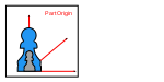
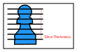
    • scan_focus [mm]: Focus distance/Magnification factor

    Laser index

    • scan_laser_index: Laser index

Multiple downskin zones

Enables setting different scan parameters depending on the downskin overhang angle.
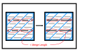
  • multiple_downskins_enable: Multiple downskin zones

    • downskin_scanning_table

      Columns:

      Max Surface Angle

      • downskin_max_surf_angle [degrees]: Max Surface Angle

      Min time

      • fill_overheat_prevention_min_time [s]: Min time

      Fill Power

      • fill_scan_power [W]: Fill Power

      Fill Speed

      • fill_scan_speed [mm/sec]: Fill Speed

      Fill Focus

      • fill_scan_focus [mm]: Fill Focus

      Fill Laser Index

      • fill_laser_index: Fill Laser Index

      Border Power

      • border_scan_power [W]: Border Power

      Border Speed

      • border_scan_speed [mm/sec]: Border Speed

      Border Focus

      • border_scan_focus [mm]: Border Focus

      Border Laser Index

      • border_laser_index: Border Laser Index